


Chapter 1. Maintenance Analysis Procedures (MAPs)
This chapter provides information for identifying problems and guides you to the most likely failed Field
Replaceable Unit (FRU). The MAPs then refer you to the FRU Removal/Replacement procedures for the
corrective action.
Switch MAPs
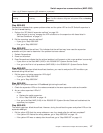
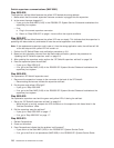
v “Switch description and problem determination (MAP 0590)”
v “Switch supervisor communications (MAP 0595)” on page 1-6
v “Switch environment (MAP 0600)” on page 1-9
v “Switch power (MAP 0610)” on page 1-13
v “Switch function (MAP 0620)” on page 1-17
Attention: Components in the frame are susceptible to damage from static discharge. Always use an
ESD wristband when working inside frame covers. (See “Personal ESD requirements” on page 3-1 for
more details.) Do not touch the pins or circuitry on these components.
Switch description and problem determination (MAP 0590)
Purpose of this MAP
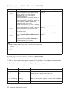
This MAP describes the components of the SP Switch2 fabric and provides a table (Table 1-1 on page 1-5)
containing diagnostic information.
Each SP Switch2 has the following components:
v Switch interposer cards
– One per occupied switch port
– Connects the SP Switch2 to a switch adapter mounted in processor node
v SP Switch2 adapter
– Installed in processor nodes
– Connects processor node to SP Switch2
Note: Systems equipped with the SP Switch2 require SP Switch2 adapters. This switch cannot
connect to the SP Switch MX2 adapter.
v Switch supervisor
v Switch power cable
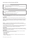
v Switch wrap plugs:
– To test systems using SP Switch2 interposer cards and adapters, use male and female wrap plugs
- Refer to Figure 1-2 on page 1-5
v Interposer wrap card:
– Used to test the SP Switch2 interposer interface
- Refer to “SP Switch2 assembly (view 2)” on page 5-4 for the interposer wrap card part number
v Switch data cables (two types):
– Internal to the frame
– External data cables (multi-frame only)
Attention: Switch data plug and jack connector pins are easily bent. Check for bent pins on male plugs
or bent pin guides on female jacks if a cable is difficult to plug. Problems with bent pins or pin guides can
propagate to new plugs and jacks if not corrected first.
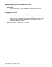
Refer to Figure 1-1 on page 1-3 for a high-level view of the RS/6000 SP SP Switch2 assembly.
© Copyright IBM Corp. 2000, 2002 1-1