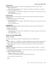
Step 0610-022
The switch’s front panel power LED remained Off after replacing the LED power extension cable.
1. Replace the switch planar.
v Refer to “Removing the switch planar” on page 4-7 and “Replacing the switch planar” on page 4-8
2. Is the front panel power LED On?
v If yes, go to Switch function (MAP 0620), “Step 0620-021” on page 1-27 and return the switch to the
active configuration.
v If no, call the next level of support.
Step 0610-023
The switch supervisor card was replaced and both the switch front panel and green switch supervisor
LEDs remain Off.
1. Replace the switch’s circuit breaker assembly.
2. Are both power LEDs On?
v If yes, go to Switch function (MAP 0620), “Step 0620-021” on page 1-27 and return the switch to the
active configuration.
v If no, go to “Step 0610-024”.
Step 0610-024
The switch’s circuit breaker assembly was replaced and both the switch front panel and green switch
supervisor LEDs remain Off.
1. Replace the switch planar.
2. Are both power LEDs On?
v If yes, go to Switch function (MAP 0620), “Step 0620-021” on page 1-27 and return the switch to the
active configuration.
v If no, call the next level of support.
Switch function (MAP 0620)
Purpose of this MAP
This MAP provides diagnostic information for problems related to the SP Switch2 function.
Notes:
1. Refer to “Appendix A” in
RS/6000 SP: Installation and Relocation
for frame-to-frame or switch-to-switch
cables. Logical frame to physical frame translation information can also be found in this appendix.
2. Refer to “Service position procedures” on page 3-10 for placing or removing the switch into or from
service position.
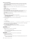
Step 0620-001
A message in Perspectives indicated that you have a switch function problem and Table 1-1 on page 1-5
directed you to this MAP.
1. To complete the following procedures, you will need to have primary node root access. (Customer may
enter root password when required.)
2. If either of the following two conditions is true:
v Estart has not been run by the customer
v The CE has already replaced components that might affect the switch.
Then from the control workstation, enter:
Estart
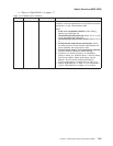
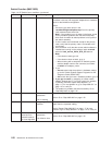
Switch power (MAP 0610)
Chapter 1. Maintenance Analysis Procedures (MAPs) 1-17


