


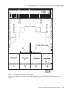

Note: In a frame with processor nodes, entries for the switch will refer to “node17” or “slot17”. In a
multi-switch frame, switches will be listed as even slot addresses.
Notes:
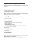
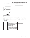
1. SP Switch2 advanced diagnostics use the 8.75 meter data cable provided by the SPS feature bill of
material.
2. Advanced cable wrap tests will not run successfully for 10-, 15-, and 20-meter SPS data cables. If
these data cables are used, change the suspected cable.
3. Refer to “SP Switch2 assembly (view 1)” on page 5-2 in Chapter 5, “Parts catalog” for the wrap plug
part numbers.
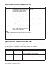
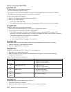
Table 1-1. Switch Problem Diagnostics
Priority Message or condition Action
1
(1 of 4)
Supervisor communication problem
v Yellow switch supervisor LED on, green LED off
v Perspectives switch pane indicates problem with
48 volts but other voltages are OK
v Perspectives switch pane shows several gray
icons with question marks
v Fans are running but green LEDs on all
interposer cards and all power supplies are off
Note: Power supply LEDs are viewable through
the fan assemblies.
Note: For information on opening a Perspectives
switch pane see: “Opening a switch pane” on
page 3-7.
Go to “Switch supervisor communications
(MAP 0595)” on page 1-6.
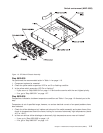
Figure 1-2. SP Switch2 Wrap Plugs
Switch Description and Problem Determination (MAP 0590)
Chapter 1. Maintenance Analysis Procedures (MAPs) 1-5