


Step 0610-004
The green switch supervisor LED is Off.
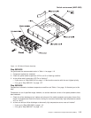
1. Make certain that the switch power cable is properly connected to jack J1 on the switch and on the
SEPBU.
2. Place the inline switch on the switch power cable into the On (‘1’) position if it is not already in that
position.
3. Place the switch circuit breaker into the On (‘1’) position if it is not already in that position.
4. Does the switch circuit breaker trip to the Off (‘0’) position?
v If yes, go to “Step 0610-005”.
v If no, go to “Step 0610-006”.
Step 0610-005
The switch circuit breaker went (tripped) to the Off (‘0’) position.
1. One at a time, remove each fan/power supply pair.
v Refer to “Removing a fan assembly” on page 4-2 and “Removing a power supply” on page 4-3.
2. After each fan/power supply pair is removed, check to see if the circuit breaker trips.
3. Does the circuit breaker still trip?
v If yes, go to “Step 0610-012” on page 1-15.
v If no, go to “Step 0610-009” on page 1-15.
Step 0610-006
The switch circuit breaker stayed in the On (‘1’) position.
1. Check the status of the green switch supervisor LED.
2. Is the green LED lit?
v If the green LED is off, go to “Step 0610-007”.
v If the green LED is on:
a. You have resolved the switch assembly problem.
b. Go to Switch function (MAP 0620) and refer to “Step 0620-021” on page 1-27 to return the
switch to the active configuration.
Step 0610-007
The switch circuit breaker is in the On (‘1’) position and the green switch supervisor LED is off.
1. Perform the “SP Switch2 supervisor self-test” on page 3-6.
2. Did the green switch supervisor LED light during the supervisor self-test?
v If yes, go to “Step 0610-008”.
v If the green LED remained off, go to “Step 0610-019” on page 1-16.
Step 0610-008
The green switch supervisor LED lights during the supervisor self-test, but not when the switch circuit
breaker is in the On (‘1’) position.
1. Place the inline switch on the switch power cable in the Off (‘0’) position.
2. Remove the power cable from jack J1 at the rear of the switch.
3. Return the inline switch on the switch power cable to the On (‘1’) position.
4. Check for 48 volts (dc) across the two power pins on the disconnected power cable.
5. Were you able to measure 48 V on the power cable?
v If yes, go to “Step 0610-019” on page 1-16.
v If no, you have a problem with 48 V dc power distribution.
–Goto″Open in 48 V dc distribution (MAP 0560)″ in
RS/6000 SP: System Service Guide
.
Switch power (MAP 0610)
1-14
RS/6000 SP: SP Switch2 Service Guide