


Step 0600-004
Perspective display shows ″Fan X: Failure″ on a red background.
1. Use Table 1-4 to service components
2. Refer to Chapter 4, “FRU removals and replacements” on page 4-1 for instructions about the
component being serviced.
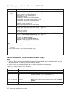
Table 1-4. Fan Failure Diagnostics
Priority Component Action
1
(1 of 6)
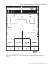
Fan 1, 2, 3, or 4
a. Check specified fans for blockages or loose
connections.
b. Fix any obvious problems and continue at “Step
0600-005” on page 1-11.
c. If you do not find any problems, continue at Priority 2.
2
(2 of 6)
Fan 1, 2, 3, or 4
a. Replace fans as described in Chapter 4, “FRU
removals and replacements” on page 4-1.
b. Continue at “Step 0600-005” on page 1-11.
3
(3 of 6)
Switch supervisor card
a. Replace the card.
b. Continue at “Step 0600-005” on page 1-11.
4
(4 of 6)
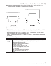
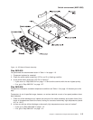
Power supply 1, 2, 3, or 4
a. Replace the power supply associated with the fan.
v Refer to Figure 1-3 on page 1-11.
b. Continue at “Step 0600-005” on page 1-11.
5
(5 of 6)
Switch planar
a. Replace planar/chassis
b. Continue at “Step 0600-005” on page 1-11.
6
(6 of 6)
All replaced Call next level of support.
Switch environment (MAP 0600)
1-10
RS/6000 SP: SP Switch2 Service Guide