


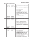


Table 1-6. SP Switch2 error conditions (continued)
Error # Device Message Link Message Description and Action
−4 Device has been
removed from
network, faulty
Link has been
removed from
network or miswire,
faulty
Description: Switch network not wired as specified in switch
topology or problem with connection between switch and
device.
Note: You may get this error number for a jack which could
connect to a node, but instead has a wrap plug. In this case,
this message is a warning only and can be ignored.
Action:
1. Check the cable_miswire file in
var/adm/SPlogs/cssX/p0 (where X=0 or 1) and rewire
the cable as needed.
2. If the cabling does not match, correct the cabling
problem, then go to step 5 below.
3. If this occurs on all nodes of a frame, check for a
logical-to-physical frame number mismatch.
4. If there is a mismatch, have the customer update the
configuration, or you can correct the cabling, as
appropriate.
5. Go to “Step 0620-004” on page 1-22.
−5 Device has been
removed from
network by system
administrator
Link has been
removed from
network by system
administrator
Description: Node was fenced from the network.
Action: run Eunfence for the node.
−6 Device has been
removed from
network, no
AUTOJOIN
Link has been
removed from
network, no
AUTOJOIN
Description: AUTOJOIN was not selected for node during
removal.
Action:
1. If there is an obvious problem, like node powered off or
disconnected, fix that problem first. Then issue
Eunfence for this processor node.
2. If problem was resolved, repeat “Step 0620-001” on
page 1-17 for next problem or go to “Step 0620-021” on
page 1-27 to verify fix.
3. If problem was not resolved, go to “Step 0620-004” on
page 1-22.
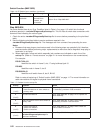
−7 Device has been
removed from
network for not
responding
Link has been
removed from
network, fenced
Description: Possible hardware problem.
Action: Go to “Step 0620-004” on page 1-22.
−8 Device has been
removed from
network because
of a miswire
Link has been
removed from
network, probable
miswire
Description: Initialization of this link detected a different
switch node number than the one expected.
Action:
1. Check the cable_miswire file in
var/adm/SPlogs/cssX/p0 (where X=0 or 1) and rewire
the cable as needed.
2. If the cabling does not match, correct the cabling
problem, then go to step 5.
3. If this occurs on all nodes of a frame, check for a
logical-to-physical frame number mismatch.
4. Have the customer update the configuration, or you can
correct the cabling, as appropriate.
5. Repeat “Step 0620-001” on page 1-17 for next problem
or go to “Step 0620-021” on page 1-27 to verify fix.
Switch Function (MAP 0620)
Chapter 1. Maintenance Analysis Procedures (MAPs) 1-21