


Switch environment (MAP 0600)
Purpose of this MAP
This MAP provides diagnostic information for switch problems that are related to the operating
environment.
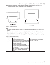
Note: Refer to “Service position procedures” on page 3-10 for placing a switch into the service position or
for removing the switch from the service position.
Step 0600-001
A switch environmental problem has been detected.
1. You have observed either:
v The yellow switch supervisor LED is on or flashing
v Perspectives switch environmental indicator is yellow or red
v Errpt message stating,“Warning”, “Shutdown”, or “Failure”
2. If:
v The yellow switch supervisor LED is on, or the Perspectives environmental indicator is yellow, or
the Errpt message states “Warning”, go to “Step 0600-002”.
v The yellow switch supervisor LED is flashing, or the Perspectives environmental indicator is red, or
the Errpt message states “Shutdown” or “Failure”, go to “Step 0600-003”.
Step 0600-002
You received a switch environment “Warning”.
1. Does this same message occur on other switches or on any processor nodes mounted in the same
frame as this switch?
v If yes, call the next level of support.
v If no, verify that the customer is not experiencing problems with this switch.
– If no problems are being experienced, or this is an N+1 fan or power supply failure, then no
immediate service is required, and service can be deferred until a later date.
– If problems are being experienced, and the customer will allow power on service, service can be
performed now by treating the problem as an Errpt message of “Shutdown” or “Failure” and
going to “Step 0600-003”.
Step 0600-003
A critical power or environmental problem has been detected and the switch has logically powered off.
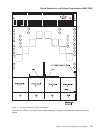
1. If service action has just been completed on this switch, check for loose cables or shorted conditions.
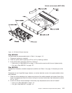
2. Record the locations of all failing FRUs (multiple FRUs may be reported).
Note: Fans are N+1 devices; two fans off will power off the SP Switch2. Power Supplies are N+2;
three power supplies off will power off the SP Switch2. Therefore, fix all fan problems before
troubleshooting power supply problems.
3. Power off the switch using the rear 48 V circuit breaker. Remember to turn on the circuit breaker when
the repair has been completed.
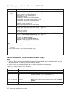
4. Based on the text of the message, use the information in Table 1-3 to continue service.
Table 1-3. Perspectives SP Switch2 status indicators
Condition Action
“...P48OK...” Go to “Switch power (MAP 0610)” on page 1-13.
Fan 1, 2, 3, or 4 indicator is red Go to “Step 0600-004” on page 1-10.
Temperature indicator is red Go to “Step 0600-006” on page 1-11.
Power Supply 1, 2, 3, or 4 indicator is red Go to “Step 0600-010” on page 1-12.
Switch environment (MAP 0600)
Chapter 1. Maintenance Analysis Procedures (MAPs) 1-9