


SP Switch2 service procedures
CAUTION:
The unit weight exceeds 18 Kg (40 lbs) and requires two service personnel to lift. (
SPSFC002
)
Note
This chapter describes removal and replacement procedures for the following SP Switch2 FRUs:
v Circuit breaker assembly
v LED bracket assembly
v LED power extension cable
v Switch supervisor card
v Power supplies
v Fan assemblies
v Switch planar assembly
v Interposer cards
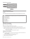
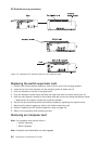
Removing a fan assembly
Note: The fan assembly is hot-pluggable.
Note: Refer to “Handling static-sensitive devices” on page 4-1.
1. Unscrew the fan assembly mounting screws located on the front of the switch chassis.
2. Grasp the fan assembly’s grill-work flange and remove the assembly by pulling it out of the chassis.
Note: If the fan assembly contains the LED bracket assembly, remove the assembly and save it for
use with the new fan assembly.
v Refer to “Removing the LED bracket assembly” on page 4-4.
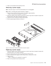
Replacing a fan assembly
Note: If the failed fan assembly contained the LED bracket assembly, reinstall the saved assembly into
the new fan assembly.
v Refer to “Replacing the LED bracket assembly” on page 4-4.
1. Insert and seat the fan assembly into the switch chassis.
2. Tighten the assembly’s mounting screws.
Figure 4-1. Handling an anti-static device
SP Switch2 service procedures
4-2
RS/6000 SP: SP Switch2 Service Guide