


Cable routing
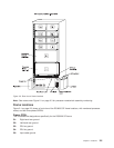
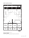
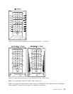
Figure 2-6 on page 2-9 and Figure 2-7 on page 2-9 show back views of the RS/6000 SP frame, showing
the horizontal and vertical paths of cable routing from connector-to-connector, with the depth amplified on
the drawing.
Note: When attaching exterior and interior cables to a POWER3 SMP High Node allow for enough cable
for a 2-foot service loop for node movement into service position.
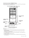
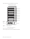
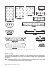
Figure 2-5. RS/6000 SP connector details (as seen at receiving ends, not at cable ends)
2-8 RS/6000 SP: SP Switch2 Service Guide