


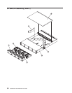
Replacing the switch planar
Attention: Replacement of the switch planar involves the replacement of the removed switch’s externally
accessible plug-ins into a new, partially populated switch planar-in-chassis assembly.
1. Remove all fan assemblies from the new switch planar assembly.
v Refer to “Removing a fan assembly” on page 4-2.
2. Install the components from the old switch into the new chassis assembly in the following order:
a. Replace the switch supervisor card.
v Refer to “Replacing the switch supervisor card” on page 4-6.
b. All interposer cards.
v Refer to “Replacing an interposer card” on page 4-7.
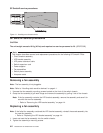
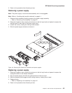
c. All power supplies.
v Refer to “Replacing a power supply” on page 4-3.
d. All fan assemblies.
v Refer to “Replacing a fan assembly” on page 4-2.
3. Replace the switch from service position.
v Refer to “Replacing an SP Switch2 from service position” on page 3-11.
4. Return to the procedure that directed you here.
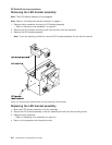
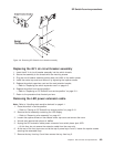
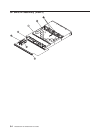
Removing the 48 V dc circuit breaker assembly
Note: Refer to “Handling static-sensitive devices” on page 4-1.
1. Place the switch in service position.
v Refer to “Placing an SP Switch2 into service position” on page 3-10.
2. Remove the switch supervisor card from slot J2.
v Refer to “Removing the switch supervisor card” on page 4-5.
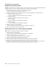
3. Remove the circuit breaker assembly mounting screws.
4. Loosen the captive screws on the chassis center top-cover and remove the cover.
5. Unplug the circuit breaker assembly power cable from J48V on the switch planar.
6. Grasp the circuit breaker bracket with one hand, apply finger pressure at its base from the empty J2
slot with the other hand, and remove the assembly by pulling it out of the chassis.
SP Switch2 service procedures
4-8
RS/6000 SP: SP Switch2 Service Guide