


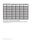
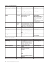
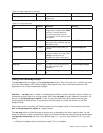

Table 2-1. External cable routing
Slot Number
(Node)
Cable Budget
millimeters (inches)
Frame
Entrance (New
Style)
Frame Entrance
(Old Style)
Vertical Routing
(Old Style)
Horizontal
Routing (Old
Style)
1 1800 (71) E3 E1 V4 H3
2 1500 (59) E3 E1 V4 H3
3 1680 (66) E3 E2 V5 H4
4 1980 (78) E3 E2 V5 H4
5 2160 (85) E3 E1 V3 H5
6 1850 (73) E3 E1 V3 H5
7 2030 (80) E3 E2 V6 H6
8 2340 (92) E3 E2 V6 H6
9 2510 (99) E3 E1 V2 H7
10 2210 (87) E3 E1 V2 H7
11 2390 (94) E3 E2 V7 H8
12 2690 (106) E3 E2 V7 H8
13 2870 (113) E3 E1 V1 H9
14 2570 (101) E3 E1 V1 H9
15 2740 (108) E3 E2 V8 H10
16 3050 (120) E3 E2 V8 H10
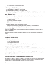
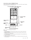
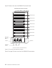
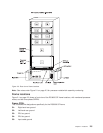
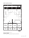
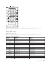
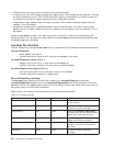
Cable routing in a multi-switch frame (F/C 2032)
Figure 2-8 on page 2-11 shows the back view of the RS/6000 SP multi-switch frame with frame extension,
showing the horizontal and vertical paths of cable routing from connector-to-connector. The depths has
been amplified on the drawing.
2-10 RS/6000 SP: SP Switch2 Service Guide