


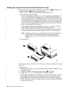
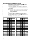
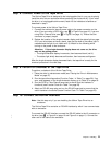
Setting the Loop ID to Provide Status About the Loop
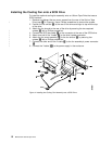
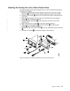
If Feature Switch 3 on the Ultrium Tape Drive is set to off (see 1 in Figure 6), the
LID/status connector 2 has the following definition:
v Pins 1, 2, 3, 4, 7, and 8 are inputs and are used to set the LID.
v Pins 5 and 6 are used as outputs:
– Pin 5 has three states: off (ground), on (3.3 V), and alternating (between off
and on). If the drive does not detect light on the Fibre Channel connector or
has not completed the Loop Initialization Protocol (LIP), pin 5 will be off. If the
drive detects light and successfully completes the LIP process, the pin will be
on. After the drive has completed the LIP process, the pin will be alternating
when the drive is receiving SCSI commands, and the pin will be on when the
drive is not receiving SCSI commands.
– Pin 6 indicates that the drive detects light. If pin 6 is on but pin 5 is off, this
could indicate communication problems across the fiber cable.
– If the drive is installed in an enclosure, pins 5 and 6 may be used to support
external indicators, such as light-emitting diodes (LEDs), on the enclosure.
Note: If indicators are used on an enclosure, the drive does not report error
codes 8 and F (Fibre Channel problems) to the single-character
display. Instead, pins 5 and 6 signal to the indicators that there is a
problem.
v Pin 9 is ground.
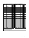
To set the AL_PA:
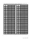
1. Determine an unused AL_PA for the drive and refer to Table 3 on page 17 for its
corresponding LID.
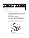
2. Locate the LID/status connector on the drive (see 2 in Figure 6).
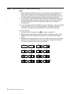
3. Jumper pins 1, 2, 3, 4, 7, and 8 as shown in Table 3 on page 17.
By using hard addressing, you can specify one of 62 valid AL_PAs for the drive.
If you jumper all of the pins, the drive gets the AL_PA from a field in its vital
product data (VPD). (An enclosure can set the AL_PA in the VPD through the
RS-422 interface.) If you do not jumper any pins, the drive uses soft addressing
to determine the AL_PA.
a67e0047
1
2
1
9
Figure 6. Setting the Loop ID and the AL_PA. The feature switches are located on the bottom
of the drive.
16 IBM Ultrium Internal Tape Drive
|
|
|
|
|
|
|
|
|
|
|
|
|
|
|
|
|
|
|
|
|
|
|
|
|
|
|