


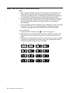
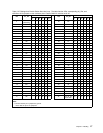
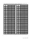
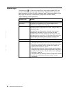

Table 4. ID Settings that Provide Additional Loop IDs (continued). The table lists the LIDs, corresponding AL_PAs,
and definitions of the jumpers on the connector pins. Feature Switch 3 must be set to ON.
LID AL_PA
PIN
LID AL_PA
PIN
1234567 1234567
5F 3C G - GGGGG 7E SA GGGGGG -
60 3A GG----- 7F SA GGGGGGG
Notes:
1. G means that the pin is jumpered to ground.
2. - means that the pin is not jumpered.
3. SA means soft addressing.
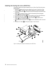
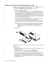
Step 7. Mount the Tape Drive into an Enclosure
Notes:
1. In the following procedure, you may find it easier to connect the cables to the
back of the tape drive (as described on pages 21 through 22) before you secure
it to the enclosure.
2. The Ultrium Tape Drive may be shipped with or without a front bezel (see
Figure 1 on page 1).
To mount the Ultrium Tape Drive into an enclosure:
1. Place the drive into the enclosure so that its tape load compartment faces the
tape load compartment of the enclosure.
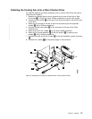
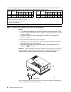
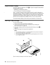
2. Insert two 6-32 screws into the mounting holes on the side brackets of the
chassis (see 2 in Figure 7).
Attention: When inserted into the Ultrium Tape Drive, the length of the mounting
screws must not exceed 2.0 mm (0.08 in.) from the outside of the chassis. If the
length exceeds this measurement, the tape drive may become damaged.
a67b0005
2
1
< 2 mm (0.08 in.)
Figure 7. Mounting Holes on Ultrium Tape Drive. The holes are located on both sides of the
drive. The tape drive is shown with a front bezel.
20 IBM Ultrium Internal Tape Drive
|
|
|
|