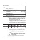
In each case, a single dc-to-dc converter converts voltage to +24 V dc and +5 V dc.
An auto-switch circuit on the interface card senses the operating mode (RS-485,
EIA-232, powered USB, or standard USB with power brick) and routes input
voltages appropriately.
v When operating in RS-485 mode, the +38 V dc is converted to +24 V dc and the
+5 V dc is passed straight through.
v When operating in EIA-232 or USB mode, the +24 V dc is passed through and is
also converted to +5 V dc.
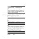
Note: Both voltage sources should not be connected to the printer at the same
time, even if one of the sources is powered off. System damage could occur
under these conditions.
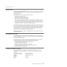
RS-485 serial I/O parameters
Printer Address
35
AWAIT-60H
extra stop bits (after printer address)
BWAIT-48H
extra bits/byte (after printer data bytes)
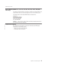
For more information about serial I/O communications, see 4680 Store Systems
Serial I/O Channel Attachment Information, which is available from IBM Industry
Corporate Relations.
Cash drawer connector pin assignments
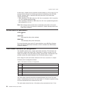
The SureMark printers have a single cash drawer connector. This connector can
drive either a single cash drawer (see “Description of models” on page 4 for the
cable part number) or two cash drawers using a special cable. The connector also
provides a status line which indicates if one of the cash drawers is open.
Drive voltage for each cash drawer solenoid is 24 V dc at a current of 1 ampere.
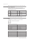
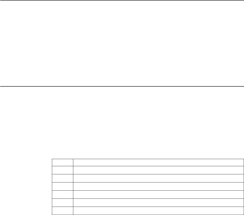
Connector pins are assigned as follows:
Table 7. Cash drawer connector pin assignments
Pin Signal
1 Not Connected
2 Solenoid 1 Driver
3 Cash Drawer Status
4 +24Vdc
5 Solenoid 2 Driver
6 Ground
The cash drawer solenoids should be connected between pins 4 and 2 for cash
drawer 1 and between pins 4 and 5 for cash drawer 2. A Y-cable is required to bring
out all the appropriate lines to attach the two units.
The cash drawer status line has a 10k resistor pull-up connected to the +5 V dc.
Updated April 2, 2009
90 SureMark Printers User’s Guide


