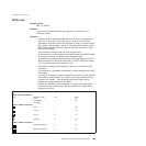
tag data. In this case, only the Compression, Size1, and Size2 fields
contain data. The header has the following format:
v Status; 1 byte
– Bit 7, Image read; 1 = image has been read, 0 = image has not been
read
– Bit 6, 1= IQD (Image Quality Detection) Error
– Bits 5–0; Reserved
v Compression; 1 byte
– Bits 7–5; Reserved
– Bits 4–0; Algorithm used to compress image. See “Select
compression format and scanned image threshold” on page 174
command
v Size1; 4 bytes
– Number of bytes in image, not including tag data.
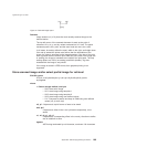
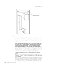
v Size2; 4 bytes (x1, y1)
– Width of image in the x direction (in hundredths of inch increments), 2
bytes
Note: Scanner resolution is 200 dots per inch.
– Height of image in the y direction (in hundredths of inch increments),
2 bytes
v Block position; 1 byte
– Lower four bits indicate the number of blocks that were saved for the
image.
– Upper four bits represent the current block number.
v Future; 1 byte
– Reserved
v Tag data
– ASCII data supplied by the application, terminated by a null string.
Offset (n2) = X'FF FF FF FF' with size (n3) = X'FF FF'sets to 0 the Image
Read bit in the specified image header.
For stored images (n1>0), the image data format is the format that was
active when the image was stored.
For immediate images (n1=0), the image data format is the currently
selected format.
Error conditions:
If any parameter is out of range, Command Reject is returned.
Scanner calibration
EIA-232 syntax:
GSc0orX'1D 63 30'
Purpose:
Used to initiate the calibration routine for the scanner. The printer scans the
document multiple times and updates the printer’s calibration data. See
“Document scanner calibration (Models TI8, TI9, TG8, TG9)” on page 60 for
more information about the document to be used.
Updated April 2, 2009
Appendix D. EIA-232 programming information 173


