


Description 13
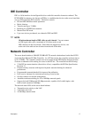
Server Board Connector and Component Locations
A
B
OM08561
C
D
EFGH I J
K
L
M
N
O
P
Q
RSTUVW
X
Y
Z
AA
BB
CC
DD
EE
FF
GG
HH
II
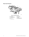
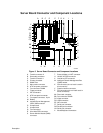
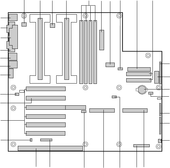
Figure 5. Server Board Connector and Component Locations
A. Fansink connector 2
B. Secondary processor
C. Fansink connector 1
D. Primary processor
E. DIMM slots
F. Main power connector
G. ATX aux power connector
H. Fan connector FAN2A
I. Floppy connector
J. IDE connectors
K. ATX front panel connector
L. Front panel connector, 16 pin
M. Battery
N. Isolated Server Management
(ISOL) IMB connector
O. Jumper block
P. Jumper block
Q. Fan connector 1
R. Ultra wide SCSI connector
S. Server Monitor Module (SMM)
connector
T. External Wake on LAN
†
connector
U. Ultra2/LVD SCSI connector
V. Hard drive LED connector
W. Intelligent Chassis Management Bus
(ICMB) header
X. ISA connector (do not install a card in
this connector)
Y. Chassis intrusion connector
Z. PCI connectors (do not install cards in
these connectors)
AA. Riser card connector
BB. Fan connector FAN2B
CC. Video connector
DD. USB connectors
EE. NIC connector
FF. Serial port connector
GG. Parallel port connector
HH. Serial port connector
II. Mouse/keyboard connectors