32 ISP2150 2U Rack Server Platform Product Guide
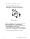
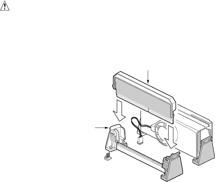
CAUTION, SINGLE-PROCESSOR CONFIGURATIONS
If you install only one processor in a system, it must go in the primary
connector (closest to the DIMM sockets). With a single-processor
configuration, you must install a termination board and termination latch
assembly (A) in the empty secondary connector (B) to ensure proper
operation of your system. A termination board is provided with your system.
OM09328
B
A
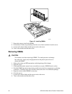
Figure 9. Installing a Termination Board
A. Terminator Latch Assembly (TLA)
B. Secondary retention mechanism
Removing a Processor
If your server has one processor and you are REPLACING it, leave the termination board intact in
the secondary connector. Remove the processor you want to replace. If your server has two
processors and you are REPLACING one or both, remove the appropriate one(s).
1. Observe the safety and ESD precautions at the beginning of this chapter and the additional
cautions given here. If the processor has a fan heat sink, disconnect the power wire (E in
Figure 8) from the connector on the server board (F in Figure 8).
2. As you work, place boards and processors on a grounded, static free surface or conductive
foam pad.
3. Press the processor latches away from the center of the S.E.C. cartridge (A in Figure 8) to free
them from the retention module (B in Figure 8).
4. Lift the S.E.C. cartridge upward, out of the retention module.
5. Put the processor in a piece of conductive foam and store in an anti-static package.


