IXD1110 Demo Board
10 Development Kit Manual
Document Number: 250807
Revision Number: 003
Revision Date: June 27, 2003
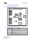
S1 Reset Switch: This switch resets the entire board when pressed.
SPI4-2 Interface
Connector
Allows a loopback connection when the loopback module is installed. This connector
can also interface with alternate SPI4-2 connections.
Mictor Connectors A,
C, and D
1
Provide access to selected IXF1110 signals. Refer to Section 8.4, “Mictor Connectors”
on page 21 for more information.
GBIC Connectors These connectors allow for SFP modules (Agilent* HFBR-5710L).
FPGA
Converts the IXF11110 asynchronous CPU signals into a synchronous format. Refer
to Section 4.1, “CPU FPGA” on page 14 for more information.
EPROM EPROM is used to program the FPGA.
Table 1. Intel
®
IXD1110 Demo Board Principal Components (Continued)
Component Description
1. For evaluation of the signals provided by the Mictor connector, use the corresponding logic analyzer probe.


