


IXD1110 Demo Board
Development Kit Manual 13
Document Number: 250807
Revision Number: 003
Revision Date: June 27, 2003
4.0 CPU Daughter Card
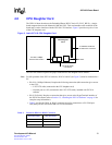
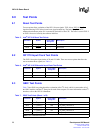
The IXD1110 demo board uses the Embedded Planet* RPX Classic LF (CLLF_BW31), a single-
board computer that uses the Motorola* MPC860 CPU. This card attaches to the underside of the
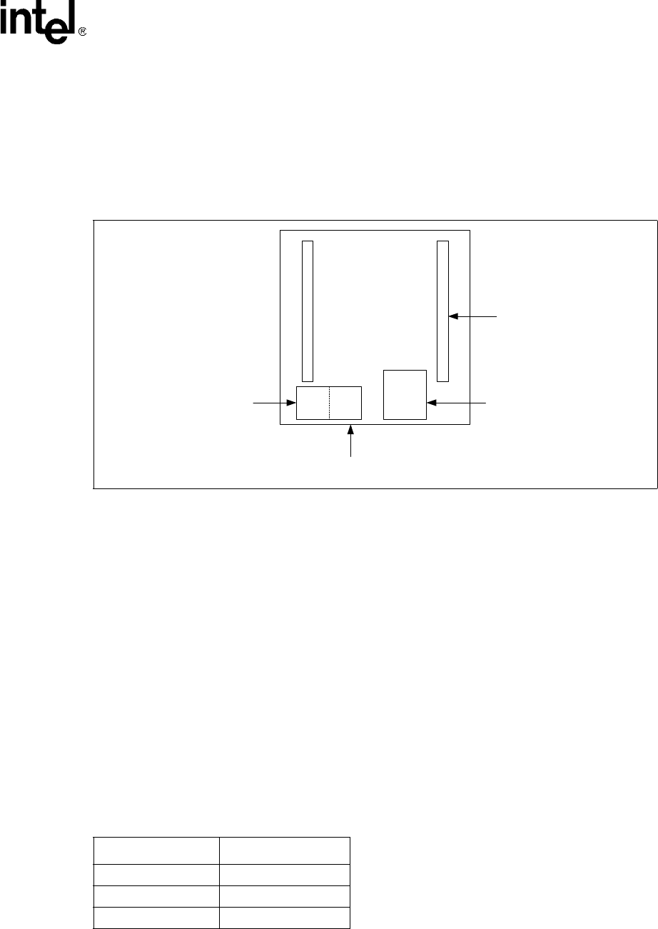
board and is used to interface with the IXF1110 CPU interface. Figure 3 provides a top-level view
of the CPU daughter card.
The IXF1110 software requires the proper connections to the daughter card as follows:
Note: For full operation of the IXF1110 software, RJ-45 #1 and #2 (see Figure 3) must be connected to a
PC.
• RJ-45 #1 (10 Mbps Ethernet): Requires the following connection (this connection gives access
to the GUI):
— CAT5-UTP cable (connected to the CPU daughter card)
— Network port on a PC (connected to the CAT5-UTP cable), installed with IXF1110
software
• RJ-45 #2 (Serial): Requires a connection that gives access to the HyperTerminal interface of
the IXF1010 software (refer to Section 5.2, “Installing the IXF1110 Software” on page 16 for
complete setup information).
• Table 2 provides the DB-9–to–RJ-45 connector pinout for connection to a PC COM port.
Only three pins are used for the DB-9–to–RJ-45 connector.
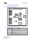
Figure 3. Intel
®
IXF1110 CPU Daughter Card
CPU Daughter
Card
RJ-45 #1 10Mbps
Ethernet Connection
RJ-45 #2 Serial
Connection
Not Used
IP Address located on
the side of the connector
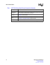
Table 2. Pinout for DB-9–to–RJ-45 Connector
RJ-45 Pin Number DB-9 Pin Number
45
53
62