IXD1110 Demo Board
18 Development Kit Manual
Document Number: 250807
Revision Number: 003
Revision Date: June 27, 2003
6.0 Optional Configurations
6.1 Reset Jumper JP2
6.1.1 Standard Operation
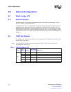
The Reset Jumper JP2 is required for standard operation of the IXD1110 demo board. Use the
HRESET position for standard operation.
The POR position is not recommended for standard operation of the IXD1110 demo board. This
configuration only affects the CPU operation, and does not affect IXF1110 operation. The only
difference between HRESET and POR is that POR also resets the CPU PLLs and state machines.
This difference is seen when reset is asserted by pressing switch S1. For more information on the
POR position of JP2, refer to Table 12 (MPC860 Reset Responses) of the Motorola* MPC860 CPU
Datasheet.
6.2 JTAG Test Signals
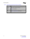
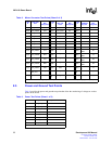
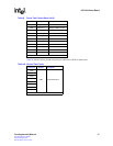
The boundary scan test port for the IXF1110 is accessed using JP1 for board-level testing. Table 3
describes JTAG test signals.
Note: For normal IXD1110 demo board operation, connect TRST_N pin 8 on JP1 to ground by
jumpering pins 6 and 8 of JP1.
Table 3. JTAG Test Signals (JP1)
Jumper
Pin
Number
Symbol
IXF1110 Ball
Designator
Description
JP1
1 TDI AC18 Test Data Input
3 TDO Y24 Test Data Output
5 TMS T16 Test Mode Select
7 TCLK AA29 Test Clock
8 TRST N18 Test Reset (jumper pins 6 and 8)
2,4,6 GND – Connect to system ground


