


4 Development Kit Manual
Document Number: 250807
Revision Number: 003
Revision Date: June 27, 2003
Contents
Figures
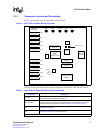
1Intel
®
IXD1110 Demo Board (Top View)...............................................................9
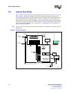
2 Typical Test Setup .............................................................................................12
3Intel
®
IXF1110 CPU Daughter Card....................................................................13
4Intel
®
IXD1110 Demo Board Power (Revision A1) .............................................25
5Intel
®
IXD1110 Digital Power ..............................................................................26
6Intel
®
IXD1110 Analog Power.............................................................................27
7Intel
®
IXD1110 Control........................................................................................28
8Intel
®
IXD1110 SerDes GBIC Ports 0-2..............................................................29
9Intel
®
IXD1110 SerDes GBIC Ports 3-5..............................................................30
10 Intel
®
IXD1110 SerDes GBIC Ports 6-8..............................................................31
11 Intel
®
IXD1110 SerDes GBIC Port 9...................................................................32
12 Intel
®
IXD1110 SPI4-2 ........................................................................................33
13 Intel
®
IXD1110 LEDs...........................................................................................34
14 Intel
®
IXD1110 CPU Interface Control ................................................................35
15 Intel
®
IXD1110 CPU Connectors ........................................................................36
16 Intel
®
IXD1110 CPU Logic Probe Connectors ....................................................37
Tables
1Intel
®
IXD1110 Demo Board Principal Components.............................................9
2 Pinout for DB-9–to–RJ-45 Connector .................................................................14
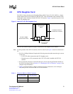
3 JTAG Test Signals (JP1).....................................................................................18
4 IXF1110 LED Behavior .......................................................................................19
5Intel
®
IXF1110 Reset Test Points .......................................................................20
6Intel
®
IXF1110 Differential Input Clock Test Points.............................................20
7 GBIC Test Points ................................................................................................20
8 Mictor Connector Test Points..............................................................................21
9 Power Test Points...............................................................................................22
10 Ground Test Points .............................................................................................23
11 Unused Test Points.............................................................................................24
12 Intel
®
IXD1110 Demo Board Bill of Materials (Rev. A1)......................................38