


IXD1110 Demo Board
22 Development Kit Manual
Document Number: 250807
Revision Number: 003
Revision Date: June 27, 2003
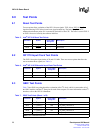
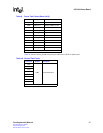
8.5 Power and Ground Test Points
Table 9 provides the power and ground test points that allow the monitoring of voltages at various
points on the board.
A2(3) uPx_Data19 A12 C2(3) uPx_Add3 H1 D2(3) –
A2(4) uPx_Data20 A15 C2(4) uPx_Add4 E3 D2(4) –
A2(5) uPx_Data21 G13 C2(5) uPx_Add5 E2 D2(5) –
A2(6) uPx_Data22 B16 C2(6) uPx_Add6 G1 D2(6) –
A2(7) uPx_Data23 E15 C2(7) uPx_Add7 C3 D2(7) –
A3(0) uPx_Data24 G14 C3(0) uPx_Add8 F5 D3(0) –
A3(1) uPx_Data25 A16 C3(1) uPx_Add9 F1 D3(1) –
A3(2) uPx_Data26 C17 C3(2) uPx_Add10 C2 D3(2) –
A3(3) uPx_Data27 A17 C3(3) – D3(3)
TxPause
Add3
K1
A3(4) uPx_Data28 B18 C3(4) – D3(4)
TxPause
Add2
J2
A3(5) uPx_Data29 A21 C3(5) – D3(5)
TxPause
Add1
G2
A3(6) uPx_Data30 B22 C3(6) – D3(6)
TxPause
Add0
G3
A3(7) uPx_Data31 C23 C3(7) IRQ – D3(7)
TxPause
Fr
J7
CLK_
0
Bus_CLK –
CLK_
3
–Q0––
CLK_
1
–Q1–
CLK_
2
––
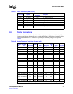
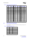
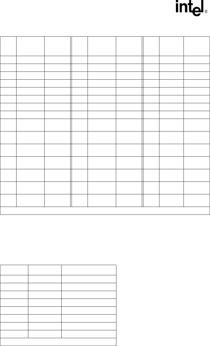
Table 8. Mictor Connector Test Points (Sheet 2 of 2)
Probe
A
CPU Data
Bus
IXF1110
Ball
Designator
Probe
C
Address
Bus and
Other
IXF1110
Ball
Designator
Probe
D
Pause I/F
and Reset
Signals
IXF1110
Ball
Designator
1. For evaluation of the signals provided by the Mictor connector, use the corresponding logic analyzer probe.
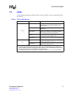
Table 9. Power Test Points (Sheet 1 of 2)
Test Point Symbol Description
TP2 Vdd_1P8_IXF 1.8 V for IXF1110
TP3 Vdd_2P5_IXF 2.5 V for IXF1110
TP4 TxA25_A SerDes Tx Block A 2.5 V
TP5 PLL1_aVdd 1.8 V for PLL1
TP6 PLL2_aVdd 1.8 V for PLL2
TP8 PLL3_aVdd 2.5V for PLL3
TP9 TxA25_C SerDes Tx Block C 2.5 V
TP19 Vdd_2P5 2.5 V rest of the board
NOTE: TP = Test Point