


IXD1110 Demo Board
12 Development Kit Manual
Document Number: 250807
Revision Number: 003
Revision Date: June 27, 2003
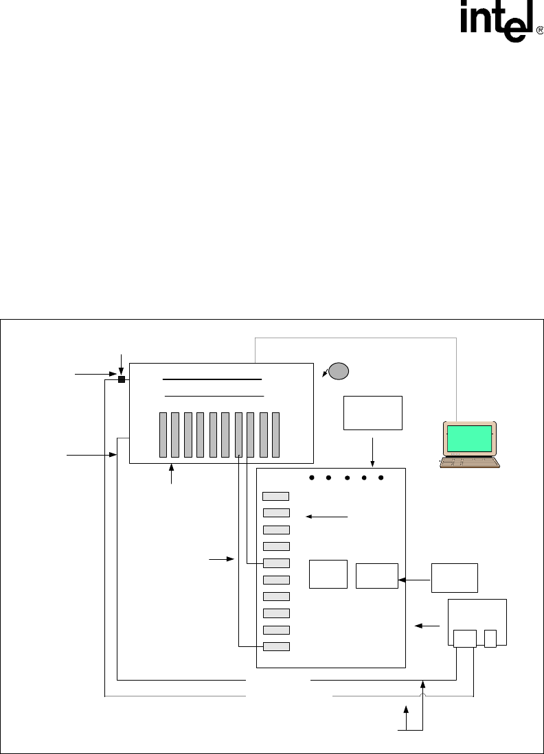
3.0 Typical Test Setup
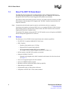
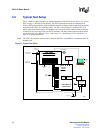
Figure 2 shows a typical test setup for standard operation of the IXF1110 (see Section 2.0, “Quick
Start” on page 11 for step-by-step details). The IXD1110 demo board can be connected to an
IXIA* 1600T packet generator with LM1000SX cards for evaluation of the board. Each port can be
connected to the IXIA* box with fiber cables. For IXF1110 software use, connect CAT5-UTP
cables to the ports shown on the CPU daughter card. One of the cables connects to the COM port
on the IXIA* box by using a DB-9–to–RJ-45 connector. The other cable connects to the network
port on the IXIA* box. Refer to Figure 2 and Section 5.2, “Installing the IXF1110 Software” on
page 16 for proper installation.
Note: The IXF1110 evaluation software can be run from the IXIA or an added PC connected to the CPU
daughter card.
Figure 2. Typical Test Setup
CPU Daughter
Card
IXIA* 1600T
Advanced Multi-port Performance Tester
Intel
®
IXD1110
Demo Board
Demo Software
GBIC SFP
Modules
Intel
®
IXF1110
Power
Supplies
Fiber Connectors
SPI4-2
Connector
Fiber
Cables
CAT5 UTP
DB-9-to-RJ-45
Connector
TCP/IP connection
UTP to Serial Connection
Connect To
Network Port
Connect to
COM port
LM1000SX
Cards
SPI4-2
Loop-back
Monitor
for IXIA
B1895