


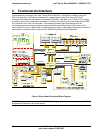
Functional Architecture Intel
®
Server Board S5000PAL / S5000XAL TPS
Revision 1.4
Intel order number: D31979-007
26
Dual-Core Intel
®
Xeon
®
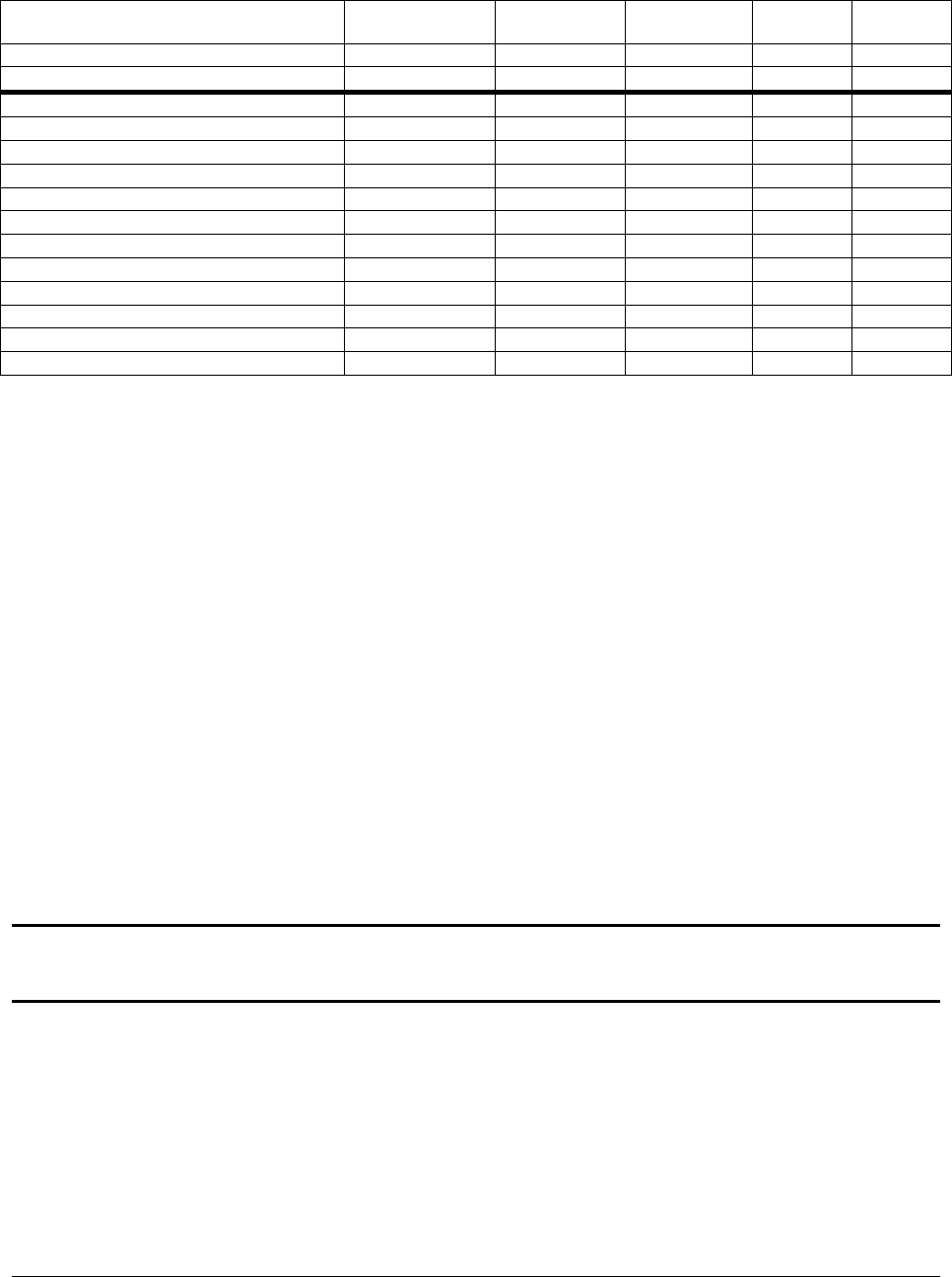
processors 5000 sequence will encompass the following:
Table 1. Processor Support Matrix
Processor Family System Bus
Speed
Core
Frequency
Cache Watts Support
Intel
®
Xeon
®
processor 533 MHz All No
Intel
®
Xeon
®
processor 800 MHz All No
Dual-Core Intel
®
Xeon
®
processor 5030 667 MHz 2.67 GHz 2x 2 MB 95 Yes
Dual-Core Intel
®
Xeon
®
processor 5050 667 MHz 3.0 GHz 2x 2 MB 95 Yes
Dual-Core Intel
®
Xeon
®
processor 5060 1066 MHz 3.2 GHz 2x 2 MB 130 Yes
Dual-Core Intel
®
Xeon
®
processor 5063 1066 MHz 3.2 GHz 2x 2 MB 95 Yes
Dual-Core Intel
®
Xeon
®
processor 5080 1066 MHz 3.73 GHz 2x 2 MB 130 Yes
Dual-Core Intel
®
Xeon
®
processor 5110 1066 MHz 1.60 GHz 4MB shared 65 Yes
Dual-Core Intel
®
Xeon
®
processor 5120 1066 MHz 1.87 GHz 4MB shared 65 Yes
Dual-Core Intel
®
Xeon
®
processor 5130 1333 MHz 2 GHz 4MB shared 65 Yes
Dual-Core Intel
®
Xeon
®
processor 5140 1333 MHz 2.33 GHz 4MB shared 65 Yes
Dual-Core Intel
®
Xeon
®
processor 5150 1333 MHz 2.67 GHz 4MB shared 65 Yes
Dual-Core Intel
®
Xeon
®
processor 5160 1333 MHz 3 GHz 4MB shared 80 Yes
3.1.2.1 Processor Population Rules
When two processors are installed, both must be of identical revision, core voltage, and bus/core speed.
Mixed processor steppings is supported. However, the stepping of one processor cannot be greater than
one stepping back of the other. When only one processor is installed, it must be in the socket labeled
CPU1. The other socket must be empty.
The board is designed to provide up to 130A of current per processor. Processors with higher current
requirements are not supported.
No terminator is required in the second processor socket when using a single processor configuration.
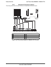
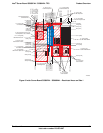
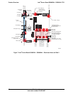
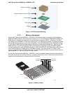
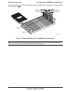
3.1.2.2 Common Enabling Kit (CEK) Design Support
The server board complies with Intel’s Common Enabling Kit (CEK) processor mounting and heat sink
retention solution. The server board ships with a CEK spring snapped onto the underside of the server
board, beneath each processor socket. The heat sink attaches to the CEK, over the top of the processor
and the thermal interface material (TIM). See the figure below for the stacking order of the chassis, CEK
spring, server board, TIM, and heat sink.
The CEK spring is removable, allowing for the use of non-Intel heat sink retention solutions.
Note: The processor heat sink and CEK spring shown in the following diagram are for reference
purposes only. The actual processor heat sink and CEK solutions compatible with this generation server
board may be of a different design.