


Connector / Header Locations and Pin-outs Intel
®
Server Board S5000PAL / S5000XAL TPS
Revision 1.4
Intel order number: D31979-007
48
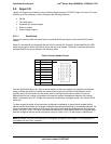
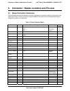
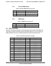
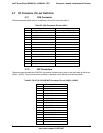
5.3.3 LCP/AUX IPMB Header
Table 16. LPC/AUX IPMB Header Pin-out (J1C2)
Pin Signal Name Description
1 SMB_IPMB_5VSB_DAT BMC IMB 5V Standby Data Line
2 GND Ground
3 SMB_IPMB_5VSB_CLK BMC IMB 5V Standby Clock Line
4 P5V_STBY +5V Standby Power
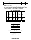
5.3.4 IPMB Header
Table 17. IPMB Header Pin-out (J1C3)
Pin Signal Name Description
1 SMB_IPMB_5VSB_DAT BMC IMB 5V Standby Data Line
2 GND
3 SMB_IPMB_5VSB_CLK BMC IMB 5V Standby Clock Line
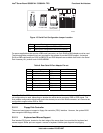
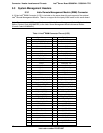
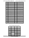
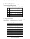
5.4 Riser Card Slots
The server board has two riser card slots. The full height riser slot (J4F1) utilizes Intel
®
Adaptive Slot
Technology. It is capable of supporting riser cards that support either the PCI-X* or PCI Express* full
height / full length add-in cards. The low profile riser slot (J5B1) supports riser cards that support low
profile PCI Express* add-in cards. The following tables show the pin-out for these riser slots.
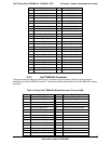
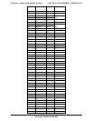
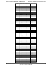
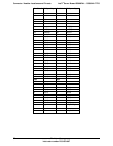
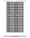
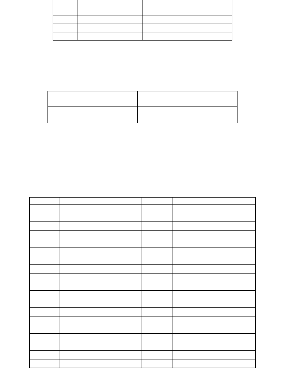
Table 18. Low-profile Riser Slot Pin-out (J5B1)
Pin Side B PCI Spec Signal Pin Side A PCI Spec Signal
1 P12V 1
2 P12V 2 P12V
3 P12V 3 P12V
4 GND 4 GND
5 SMB_PCI3V3SB_CLK 5 PD_LP_TCK
6 SMB_PCI3V3SB_DAT 6 PU_LP_TDI
7 GND 7 FP_CHASSIS_INTRU
8 P3V3 8 PU_LP_TMS
9 PD_LPTRST_N 9 P3V3
10 P3V3_AUX 10 P3V3
11 PE_WAKE_N 11 PE_RST_LP_N
12 P3V3 12 GND
13 GND 13 CLK_100M_LP_PCIE_SLOT1_P
14 PE4_MCH_TXP_C <3..0> 0 14 CLK_100M_LP_PCIE_SLOT1_N
15 PE4_MCH_TXN_C <3..0> 0 15 GND
16 GND 16 PE4_MCH_RXP <3..0> 0
17 17 PE4_MCH_RXN <3..0> 0
18 GND 18 GND
19 PE4_MCH_TXP_C <3..0> 1 19 P3V3