


Intel
®
Server Board S5000PAL / S5000XAL TPS Connector / Header Locations and Pin-outs
Revision 1.4
Intel order number: D31979-007
59
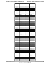
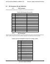
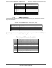
Pin Signal Name Description
10 P5V_KB_F Keyboard / mouse power
11 MS_CLK_F Mouse Clock
12 TP_PS2_12 Test point – keyboard / mouse
13 GND Ground
14 GND Ground
15 GND Ground
16 GND Ground
17 GND Ground
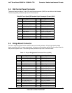
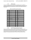
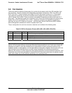
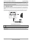
5.7.8 USB 2.0 Connectors
The following table details the pin-out of the external USB connectors (J5A1, J6A2) found on the back
edge of the server board.
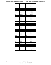
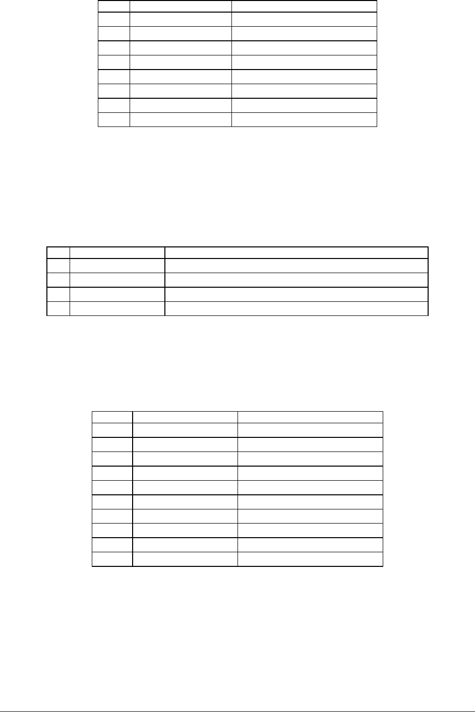
Table 30. External USB Connector Pin-out (J5A1, J6A2)
Pin Signal Name Description
1 USB_OC#_FB_1 USB_PWR
2 USB_P#N_FB_2 DATAL0 (Differential data line paired with DATAH0)
3 USB_P#N_FB_2 DATAH0 (Differential data line paired with DATAL0)
4 GND Ground
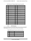
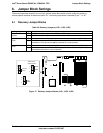
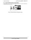
One 2x5 header on the server board (J1J1) provides an option to support an additional two USB 2.0 ports.
The pin-out of the connector is detailed in the following table.
Table 31. Internal USB Connector Pin-out (J1J1)
Pin Signal Name Description
1 P5V_USB2_VBUS0 USB Power (Ports 0,1)
2 P5V_USB2_VBUS1 USB Power (Ports 0,1)
3 USB_ESB_P0N_CONN USB Port 0 Negative Signal
4 USB_ESB_P1N_CONN USB Port 0 Positive Signal
5 USB_ESB_P0P_CONN USB Port 1 Negative Signal
6 USB_ESB_P1P_CONN USB Port 1 Positive Signal
7 Ground
8 Ground
9 -- No Pin
10 TP_USB_ESB_NC TEST POINT