Intel® Server Board S5000PAL / S5000XAL TPS List of Tables
Revision 1.4
Intel order number: D31979-007
ix
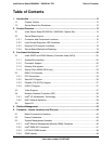
List of Tables
Table 1. Processor Support Matrix .............................................................................................26
Table 2. I
2
C Addresses for Memory Module SMB .....................................................................28
Table 3. Maximum 8 DIMM System Memory Configuration – x8 Single Rank ...........................28
Table 4. Maximum 8 DIMM System Memory Configuration – x4 Dual Rank.............................. 28
Table 5. PCI Bus Segment Characteristics.................................................................................34
Table 6. Video Modes.................................................................................................................38
Table 7. NIC2 Status LED...........................................................................................................39
Table 8. Serial A Header Pin-out ................................................................................................40
Table 9. Rear Serial B Port Adapter Pin-out...............................................................................41
Table 10. Board Connector Matrix..............................................................................................44
Table 11. Power Connector Pin-out (J3K3) ................................................................................45
Table 12. 12V Power Connector Pin-out (J3K4).........................................................................45
Table 13. Power Supply Signal Connector Pin-out (J1K1) .........................................................45
Table 14. Intel
®
RMM Connector Pin-out (J1C5) ........................................................................46
Table 15. 30-pin Intel
®
RMM NIC Module Connector Pin-out (J1B2) .........................................47
Table 16. LPC/AUX IPMB Header Pin-out (J1C2)......................................................................48
Table 17. IPMB Header Pin-out (J1C3) ......................................................................................48
Table 18. Low-profile Riser Slot Pin-out (J5B1)..........................................................................48
Table 19. Full-height Riser Slot Pin-out (J4F1)...........................................................................49
Table 20. Front Panel SSI Standard 24-pin Connector Pin-out (J3H2) ......................................53
Table 21. 120-pin Bridgeboard Connector Pin-out (J4G1) .........................................................53
Table 22. VGA Connector Pin-out (J6A1)...................................................................................55
Table 23. RJ-45 10/100/1000 NIC Connector Pin-out (JA8A1, JA8A2)......................................55
Table 24. 44-pin IDE Connector Pin-out (J3G1).........................................................................56
Table 25. 50-pin Intel
®
I/O Expansion Module Connector Pin-out (J3B1)...................................57
Table 26. SATA Connector Pin-out (J1H1, J1G2, J1G1, J1F2, J1E3) .......................................57
Table 27. External RJ-45 Serial ‘B’ Port Pin-out (J9A2) .............................................................58
Table 28. Internal 9-pin Serial ‘A’ Header Pin-out (J1B1)...........................................................58
Table 29. Stacked PS/2 Keyboard and Mouse Port Pin-out (J9A1) ...........................................58
Table 30. External USB Connector Pin-out (J5A1, J6A2)...........................................................59
Table 31. Internal USB Connector Pin-out (J1J1).......................................................................59
Table 32. SSI Fan Connector Pin-out (J9K1,J5K1,J3K1,J3K2,J7A2,J7A1) ...............................60
Table 33. Recovery Jumpers (J1D1, J1D2, J1D3) .....................................................................61
Table 34: Server Board Design Specifications ...........................................................................70
Table 35. Dual-Core Intel
®
Xeon
®
Processor 5000 Sequence TDP Guidelines per processor ..71


