


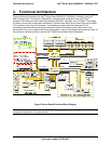

Functional Architecture Intel
®
Server Board S5000PAL / S5000XAL TPS
Revision 1.4
Intel order number: D31979-007
28
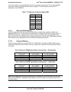
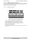
To boot the system, the system BIOS on the server board uses a dedicated I
2
C bus to retrieve DIMM
information needed to program the MCH memory registers. The following table provides the I
2
C
addresses for each DIMM slot.
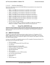
Table 2. I
2
C Addresses for Memory Module SMB
Device Address
DIMM A1 0xA0
DIMM A2 0xA2
DIMM B1 0xA0
DIMM B2 0xA2
DIMM C1 0xA0
DIMM C2 0xA2
DIMM D1 0xA0
DIMM D2 0xA2
3.1.3.1 Memory RASUM Features
i
The MCH supports several memory RASUM (Reliability, Availability, Serviceability, Usability, and
Manageability) features. These features include the Intel
®
x4 Single Device Data Correction (Intel
®
x4
SDDC) for memory error detection and correction, Memory Scrubbing, Retry on Correctable Errors,
Memory Built In Self Test, DIMM Sparing, and Memory Mirroring. See the Intel
®
S5000 Series Chipsets
Server Board Family Datasheet for more information describing these features.
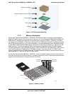
3.1.3.2 Supported Memory
The server board supports up to eight DDR2-533 or DDR2-667 Fully Buffered DIMMs (FBD memory).
The following tables show the maximum memory configurations supported using the specified memory
technology.
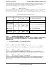
Table 3. Maximum 8 DIMM System Memory Configuration – x8 Single Rank
DRAM Technology x8
Single Rank
Maximum Capacity
Mirrored Mode
Maximum Capacity
Non-Mirrored Mode
256 Mb 1 GB 2 GB
512 Mb 2 GB 4 GB
1024 Mb 4 GB 8 GB
2048 Mb 8 GB 16 GB
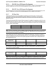
Table 4. Maximum 8 DIMM System Memory Configuration – x4 Dual Rank
DRAM Technology x4
Dual Rank
Maximum Capacity
Mirrored Mode
Maximum Capacity
Non-Mirrored Mode
256 Mb 4 GB 8 GB
512 Mb 8 GB 16 GB
1024 Mb 16 GB 32 GB
2048 Mb 16 GB 32 GB
Note: DDR2 DIMMs that are not fully buffered are NOT supported on this server board. See the Intel
®
Server Board S5000PAL / S5000XAL Tested Memory List for a complete list of supported memory for
this server board.