


Intel
®
Server Board S5000PAL / S5000XAL TPS Connector / Header Locations and Pin-outs
Revision 1.4
Intel order number: D31979-007
55
5.7 I/O Connector Pin-out Definition
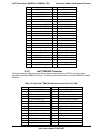
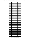
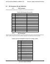
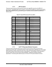
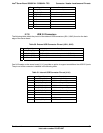
5.7.1 VGA Connector
The following table details the pin-out definition of the VGA connector (J6A1).
Table 22. VGA Connector Pin-out (J6A1)
Pin Signal Name Description
1 V_IO_R_CONN Red (analog color signal R)
2 V_IO_G_CONN Green (analog color signal G)
3 V_IO_B_CONN Blue (analog color signal B)
4 TP_VID_CONN_B4 No connection
5 GND Ground
6 GND Ground
7 GND Ground
8 GND Ground
9 TP_VID_CONN_B9 No Connection
10 GND Ground
11 TP_VID_CONN_B11 No connection
12 V_IO_DDCDAT DDCDAT
13 V_IO_HSYNC_CONN HSYNC (horizontal sync)
14 V_IO_VSYNC_CONN VSYNC (vertical sync)
15 V_IO_DDCCLK DDCCLK
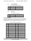
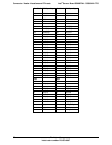
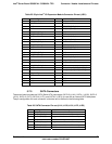
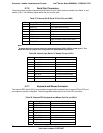
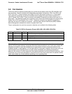
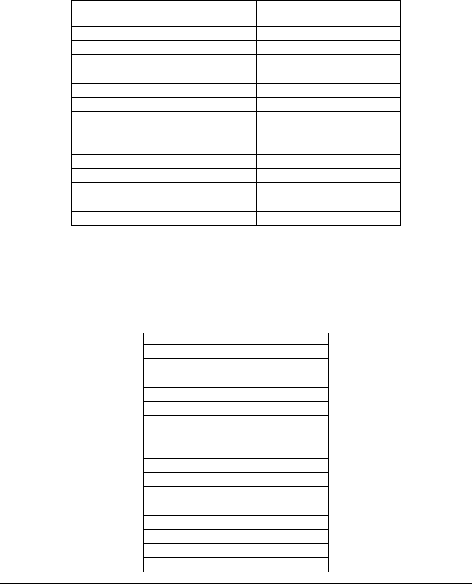
5.7.2 NIC Connectors
The server board provides two RJ45 NIC connectors oriented side by side on the back edge of the board
(JA8A1, JA8A2). The pin-out for each connector is identical and is defined in the following table.
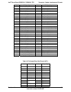
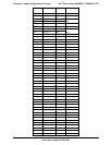
Table 23. RJ-45 10/100/1000 NIC Connector Pin-out (JA8A1, JA8A2)
Pin Signal Name
1 GND
2 P1V8_NIC
3 NIC_A_MDI3P
4 NIC_A_MDI3N
5 NIC_A_MDI2P
6 NIC_A_MDI2N
7 NIC_A_MDI1P
8 NIC_A_MDI1N
9 NIC_A_MDI0P
10 NIC_A_MDI0N
11 (D1) NIC_LINKA_1000_N (LED
12 (D2) NIC_LINKA_100_N (LED)
13 (D3) NIC_ACT_LED_N
14 NIC_LINK_LED_N
15 GND
16 GND