


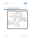

Crown Beach Board
User’s Manual 14
Document Number: 320264
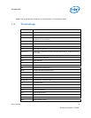
Feature Crown Beach Board
Implementation
Comments
LVDS options
Single 24-bit LVDS interface;
Back Light Inverter (BLI) and
LED backlight support
Through a 50-pin cable-up connector
(separate cables required for each
display supported).
Main Clock CK540
TSSOP, 64-pinspackage
Integrated CK-SSCD and clock
expansion buffer.
ATA/Storage PATA66/100 One desktop PATA connector
USB 8 USB 2.0 ports
4 back panel connectors
• Ports [1:0] and [4:3]
3 cable-up
• Ports [5] and [7:6]
One client-mode back panel connector
(mini-B).
• Port [2]
NOTE: All ports are enabled by default
except port 5. For more
information, refer Section 2.5.7
USB Connectors.
NOTE: Ports [7:6] are USB 2.0 only.
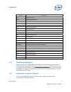
SDIO/MMC
2 ports (Ports 0 and 1), 4-bits
1 port (Port 2), 8-bits
2 SDIO back panel connectors
• Slot [2:1]
One SDIO backside connector
• Slot [0]
All slots are SDIO Revision 1.1 and MMC
Revision 4.0 compliant
NOTE: For more information, refer to
Section 2.5.12 SD/SDIO/MMC.
Soft Audio/ Soft
Modem
2 x8 option for cable-up to SDVO
for HDMI+
One Intel® HD Audio MDC
Header
Option for 3.3-V and 1.5-V operation
through jumper.
2 x4 for Mott Canyon 4 support
PCI Express* x1
connector
2 connectors
x1 connector
Revision 1.0a compliant
NOTE: Slot 1 is non-functional by
default.