


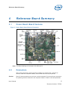

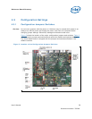

Reference Board Summary
User’s Manual 32
Document Number: 320264
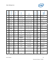
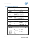
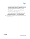
4.4 BSEL Jumper Settings
The jumper settings in Table 10 are provided to accommodate frequency selection for
the processor. The CK-540 clock chip accepts two signals from the Intel® Atom™
processor.
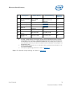
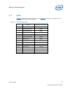
Table 10. BSEL Jumper Settings
Processor Intel® SCH
CPU Override Graphics
Processor driven
J8G3 Æ 1-2
J9G3 Æ 1-2
No override
See note.
400
(Host CLK = 100 MHz)
J8G3Æ Open
J9G3Æ 2-3
CPU BSEL 1=0
CPU BSEL 2=1
J6F1 Æ 2-3
J7F2 Æ 2-3
FSB
Speed
(MHz)
Default
533
(Host CLK = 133 MHz)
J8G3Æ Open
J9G3Æ Open
CPU BSEL 1=0
CPU BSEL 2=0
J6F1 Æ 1-2
J7F2 Æ 2-3
NOTE: Jumpers J7F2 and J6F1 must be set according to the FSB frequency to ensure 200-MHz
operation.
4.5 Manual VID Support for CPU
The Crown Beach supports manual VID operation for the processor VR. A header
(J1B1) is provided to incorporate “VID override”. VID override allows for overriding
the CPU VID outputs to the CPU VCC_CORE VR. The intent of the “VID override”
circuit is to enable debugging and testing. See Appendix B
for the VID code table.
Note: When manually overriding the VID outputs, an open jumper position will result in logic
‘1’ on the corresponding VID signal. Closing the jumper position will result in logic ‘0’
on the corresponding VID signal.