


Reference Board Summary
User’s Manual 30
Document Number: 320264
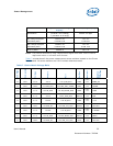
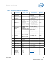
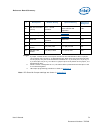
Table 9. Configuration Jumper/Switches Settings
#
Description Default Setting
1
Optional Setting Reference
Designator
1a
Remote H8
Programming
Open
1-2 (Short) – to
program H8
3
J8E1
J8E4
1b
Remote H8
Programming
(BB_PROG)
1-2 – normal operation
1-x – link the Host Unit
to On Board H8
J8D4
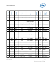
2
Virtual Battery
Switch
1-2 (UP) – normal
operation
Virtual Battery switch
is pulled high
(disabled). The system
acts as if it is running
on AC power
2-3 (DOWN) – Virtual
Battery switch is pulled
low. This enables the
virtual battery and the
system acts as if it is
running from a battery
source
SW8A1
2
3
Virtual Battery
Jumper
1-x (OUT) – normal
operation
Virtual battery status
is controlled by SW9A2
1-2 (IN) – Override
switch SW9A2 condition.
System will always act
as if it is running from a
battery source
J8A1
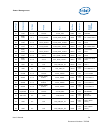
4 Lid Jumper
1-x (OUT) – normal
operation
No effect on circuit.
1-2 (IN) - Override
switch condition, pulled
low
J9A1
5 Lid Switch
1-2 (UP) – normal
operation
LID switch is pulled
high
2-3 (DOWN) – LID
switch is pulled low
SW9A1
2
6 Clear RTC
1-x (OUT) – normal
operation
1-2 (IN) to clear CMOS J4H1
7 Force Shutdown No Stuff Reserved J7G1
8a BSEL0 Setting No Stuff Reserved J8G2
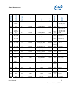
8b BSEL1 Setting
1-2 – Processor BSEL
Select
OUT – 400 MHz
OUT – 533 MHz
J8G3
8c BSEL2 Setting
1-2 – Processor BSEL
Select
2-3 – 400 MHz
OUT – 533 MHz
J9G3
9a
Manual VIDs:
VID 6 (1-2)
VID 5 (3-4)
VID 4 (5-6)
VID 3 (7-8)
VID 2 (9-10)
VID 1 (11-12)
VID 0 (13-14)
IN – normal operation
(1-2)
(3-4)
(5-6)
(7-8)
(9-10)
(11-12)
(13-14)
OUT – Refer to
Section 4.5
and
Appendix B
J1B1