


Reference Board Summary
User’s Manual 35
Document Number: 320264
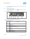
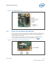
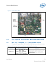
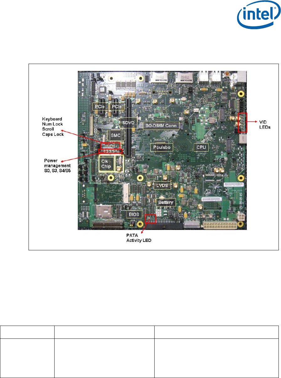
Figure 8. Crown Beach LEDs
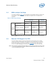
4.8 PCI Express* X1 Slots and Mini Card Connectors
4.8.1 Mini Card A connector (J7H1) is enabled by default
To enable PCI Express* Slot 1 (J8C1) Mini Card A (J7H1) must be redirected to Slot 1.
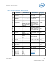
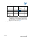
Table 12. PCI Express* Slot 1 Board Rework to Enable Functionality
Rework Impacted components Comments
Enable Slot 1
Remove – R6D1, R6D3, R6E2, R6E3,
R8F19, R8F21
Populate 0 Ohms – R6D2, R6D4,
R6E1, R6E4
Populate 33 Ohms - R8F22, R8F20
Rework provides proper connectivity for PCI
Express* Slot 1. Refer to the Mini Card A
sheet of the Crown Beach Schematics and
layout for details.