


Crown Beach Board
User’s Manual 16
Document Number: 320264
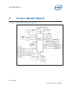
2.5 Subsystem Descriptions
Subsystem features refer to the socket and connector locations on the Crown Beach
Board. Socket and connector locations are labeled with a letter-number combination.
Refer to the silkscreen labeling on Crown Beach Board for location detail.
2.5.1 Intel® SCH Chipset
• Processor interface at 400/533 MHz
• Single channel DDR2 memory interface running at 400/533 MT/s
• Two PCI Express* ports, x1
• Eight USB 2.0 compatible ports
• One ATAPI-6 (UDMA 100MB/s) IDE channel
• Intel® HD Audio
• Three SDIO/MMC interfaces
• One channel 24-bit LVDS
• One channel SDVO
• LPC bus
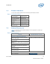
2.5.2 System Memory
• Supports a single DDR2 SO-DIMM socket. SO-DIMMs must be un-buffered and
compliant with Raw Cards A or C as defined by JEDEC.
• Supports 400- or 533-MHz memory bus frequencies.
Note: SO-DIMM support is only provided for validation purposes. The Intel® Centrino®
Atom™ Processor Technology Platform Design Guide provides component
implementations for memory down solutions. The DDR2 SODIMM Architecture’s
Implementation for Intel® System Controller Hub (SCH) US15W whitepaper provides
guidelines for implementing a SO-DIMM solution, although the recommendations are
based on simulation only and have not been validated. It is recommended that
customers validate their designs.
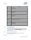
2.5.3 Display
The reference board has two options for displaying video:
• LVDS – location is J5G2
• SDVO – location is J7C2
Note: The customer reference board supports single channel LVDS only.
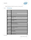
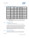
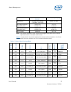
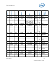
Table 4
is a listing of displays that have been tested with Crown Beach.