


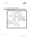
Crown Beach Board
User’s Manual 15
Document Number: 320264
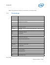
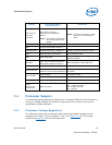
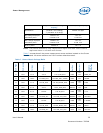
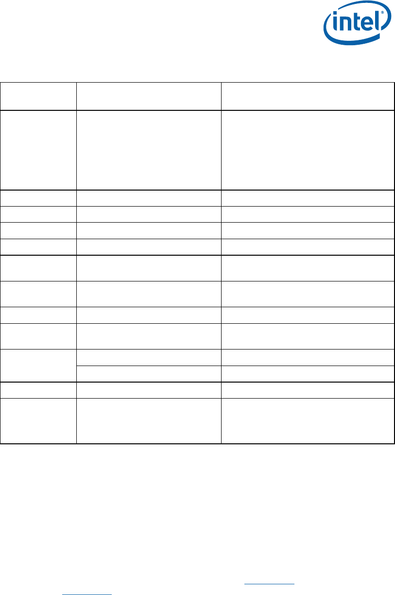
Feature Crown Beach Board
Implementation
Comments
PCI Express*
Mini Card
connector
2 connectors.
Mini Card connector A,
functionality is enabled by
default.
NOTE: PCI Express* signals are
left unconnected on Mini
Card B.
NOTE: For more information, refer to
Section 2.5.4, PCI Express*
Slots.
LPC One LPC slot No DMA support
TPM Through TPM header (TPM 1.2)
Microcontroller Renesas Technology* H8S/2117 Includes integrated SPI as an option
FWH FWH LPC based with socket 40-pin TSSOP socket
SIO Uses TPM header
Backup only; provides floppy, COM,
Parallel, and PS2
SMC/KBC
Scan matrix headers and PS/2 in
back panel keyboard connector
ACPI compliant through H8S/2117
RTC Battery-backed real time clock
Port 80 Decode
Supported down on motherboard
with four seven-segment displays
Has an option for cable-up to front panel
of chassis
Desktop Mode ATX Power Supply
Power Supply
Virtual Battery SW8A1 switch
ITP Support Extended Debug Port (XDP) J1E3 XDP connector
Power
Management
Form Factor
ACPI Compliant
S0 – Power On
S3 – Suspend to RAM
S4 – Suspend to Disk
S5 – Soft Off
2.4 Processor Support
The reference board supports the Intel® Atom™ processor Z530 with 512-KB cache in
a 441-pin, FCBGA package. No heatsink is required by this processor during room
temperature ambient operation.
2.4.1 Processor Voltage Regulators
The reference board uses an onboard Intel® MVP6 single-phase regulator for the
processor core supply. The I/O voltage is 1.05 V. See Section 4.5
for VID jumper
location and Appendix B
for the VID code table.