


User’s Manual 5
Document Number: 320264
Figures
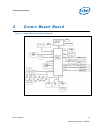
Figure 1. Crown Beach Board Block Diagram.......................................................11
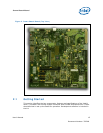
Figure 2. Crown Beach Board (Top View)............................................................12
Figure 3. Crown Beach Board Feature Placement .................................................27
Figure 4. Back Panel Connectors .......................................................................28
Figure 5. Location of the Configuration Jumpers/Switches.....................................29
Figure 6. Crown Beach Manual VID....................................................................33
Figure 7. Crown Beach Power On and Reset Buttons ............................................33
Figure 8. Crown Beach LEDs.............................................................................35
Figure 9. Samsung 15 inch (381.00 mm) Panel ...................................................40
Figure 10. Crown Beach Board..........................................................................41
Figure 11. LVDS Cable Connected to the Crown Beach Board.................................42
Figure 12. Mott Canyon 4 Interposer Card ..........................................................47
Figure 13. Front Chassis View...........................................................................53
Figure 14. Rear Chassis View with Board Installed ...............................................54
Tables
Table 1. Intel Literature Centers........................................................................10
Table 2. Related Documents. ............................................................................10
Table 3. Crown Beach Feature Set Summary.......................................................13
Table 4. Crown Beach Supported LVDS Displays..................................................17
Table 5. Power Measurement Resistor................................................................21
Table 6. Digital Multi-Meter Comparison .............................................................21
Table 7. Crown Beach Voltage Rails ...................................................................22
Table 8. Back Panel Connectors.........................................................................28
Table 9. Configuration Jumper/Switches Settings.................................................30
Table 10. BSEL Jumper Settings........................................................................32
Table 11. Crown Beach LEDs ............................................................................34
Table 12. PCI Express* Slot 1 Board Rework to Enable Functionality.......................35
Table 13. Mini Card B Board Rework to Enable Functionality..................................36
Table 14. H8 Programming Jumpers ..................................................................38
Table 15. Mott Canyon 4 Interposer Card Configuration Jumper/Switches................48
Table 16 Voltage Identification Definition............................................................50