


Quick Start
User’s Manual 43
Document Number: 320264
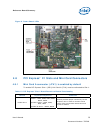
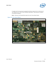
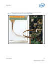
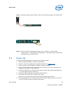
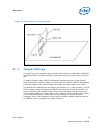
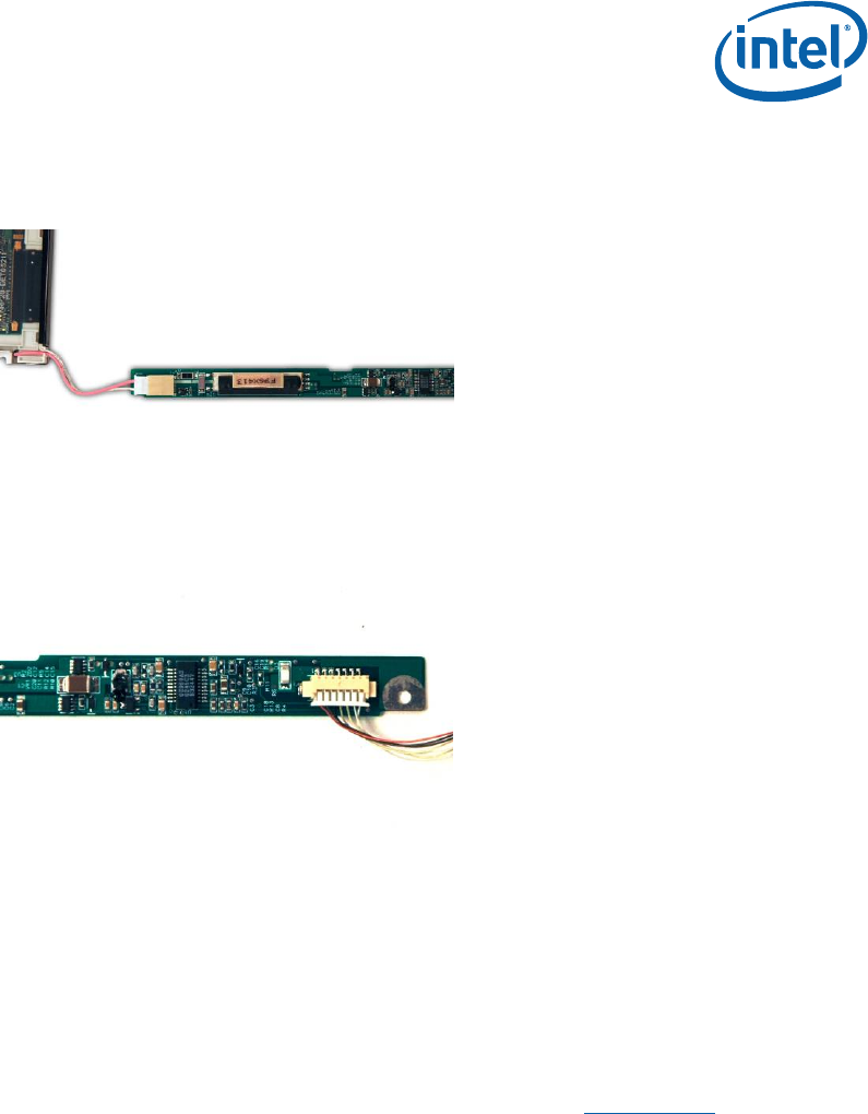
Step 3: Connect the Back Light Inverter (BLI) to the Samsung panel and LVDS cable.
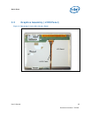
Step 4: In the Firmware Configuration Menu, go to: Chipset -> North Bridge
Configuration -> Boot Display Configuration -> Flat Panel Type to 1024x768
Samsung 15 inch (381.00 mm).
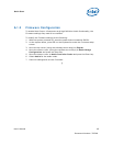
5.3 Power Up
Complete the following steps to operate the reference board.
1. Place a DDR2 SO-DIMM in memory socket J6D1.
2. Install or verify the configuration jumpers as shown in Section 4.3.1
.
3. Verify presence of RTC battery in Battery Holder at XBT5H1.
4. Plug in an ATX power supply into connectors J3J2 and J1J1; the connectors are
keyed and will only fit in one position.
5. Connect a hard drive to connector J4J3 using a PATA cable (red stripe toward pin
1). Connect ATX power to hard drive.
6. Connect a PS/2 keyboard to connector J1A2 (bottom)
7. Connect a PS/2 mouse to connector J1A2 (top)
Note: You can reverse the connections of the keyboard and mouse.
8. If internal graphics are not used, plug a PCI Express* Graphics card in the PCI-E
x1 slot J7C1 and connect a monitor to the card.