


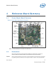
Reference Board Summary
User’s Manual 28
Document Number: 320264
by the external devices could damage the computer, the interconnecting cable, or the
attached external device.
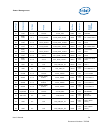
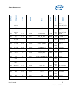
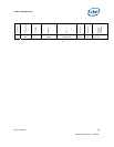
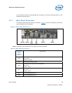
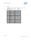
4.2.1 Back Panel Connectors
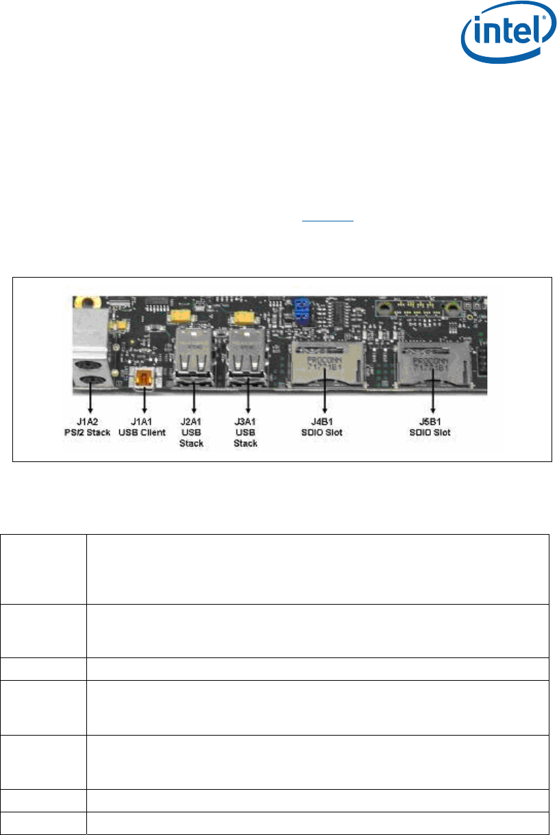
This section describes the board’s connectors. Figure 4 shows the location of the back
panel connectors on the board.
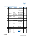
Figure 4. Back Panel Connectors
Note: Connector J1A1 USB Client is a USB 2.0 Mini-B connector.
Table 8. Back Panel Connectors
Ref Des
Back
Panel
Connector
Description
J1A2
PS/2 connector
Top: Mouse
Bottom: Keyboard
J1A1 USB Client connector, Port 2
J2A1
USB Host ports with over-current detection
Top: Port 0
Bottom : Port 1
J3A1
USB Host ports with over-current detection
Top: Port 4
Bottom : Port 3
J4B1 8-bit SD/SDIO/MMC Slot 2
J5B1 4-bit SD/SDIO/MMC Slot 1