


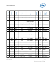
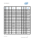
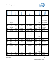
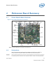
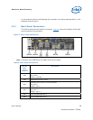
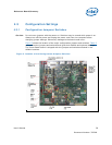
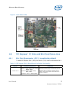

Reference Board Summary
User’s Manual 31
Document Number: 320264
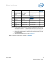
#
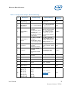
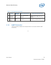
Description Default Setting
1
Optional Setting Reference
Designator
9b
VID CPU Override4
(15-16)
OUT – normal
operation
15-16 (IN) – Override to
allow manual VID
operation
J1B1
10a CFG0 Setting Refer to Section 4.4 J6F1
10b CFG1 Setting Refer to Section 4.4 J7F2
11 Reserved
OUT – normal
operation
Reserved J7F1
12 PS_ON# 1-2 – normal operation 2-3 - Reserved J7H4
13
5V FET Load
Disable
1-X (OUT) load 1-2 (IN) no load J4J1
14
12V FET Load
Disable
1-2 (IN) no load 1-X (OUT) load J5J2
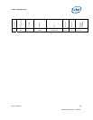
NOTES:
1. A jumper consists of two or more pins mounted on the motherboard. When a jumper
cap is placed over two pins, it is designated as IN. When there are more than two pins
on the jumper, the pins to be shorted are indicated as 1–2 (to short pin 1 to pin 2), 2–
3 (to short pin 2 to pin 3), etc. When no jumper cap is to be placed on the jumper, it is
designated as OUT.
2. When a switch is designated as 1–2, the switch slide is positioned such that pins 1 and
2 are shorted together.
3. H8 Jumper programming procedure is shown in Section 4.9
.
Note: VID Override Jumper settings are shown in Appendix B.