


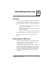
Chapter 3: Connecting to the Line
iSPAN PRI PCI ISDN Users Guide 25
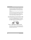
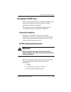
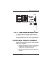
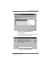
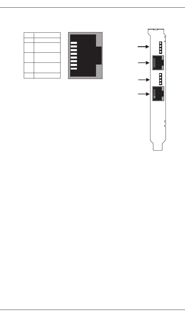
Figure 3-4. Adapter’s Faceplate and Connector Pinouts
The adapter’s connectors follow the RJ48C specification.
Four Light Emitting Diodes (LEDs) display the status of the
link (as described in Interpreting Adapter LEDs on page 67).
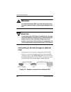
Connecting the Adapter to the Network
With the adapter installed, you are ready to connect the adapter
to the network, as follows:
1. Obtain the cable required for your type of connection, as
described in T1 Link Requirements on page 22 or
E1/PRI Cabling Requirements on page 23.
2. Attach the appropriate RJ48C-compliant connector to
the adapter.
1
2
3
4
5
6
7
8
Pin
Tx out (tip)
Tx out (ring)
Rx in (ring)
Rx in (tip)
Signal
8
1
(RJ48C)
(RJ48C)
Port #1
(Port #1)
(Port #0)
Port #0
LEDs 5, 6, 7 & 8
LEDs 1, 2, 3 & 4
RJ48C Pinout