C-4
FS-1010
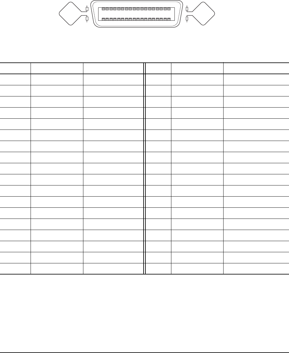
Parallel interface pin assignment
The pins of the parallel interface connector carry the signals listed below. The function for each
signal is detailed on the following page.
No. Terminal Signal No. Terminal Signal
1 nStrobe (STBIN1/2*) 19 Ground GND
2 Data1 (PAD0) 20 Ground GND
3 Data2 (PAD1) 21 Ground GND
4 Data3 (PAD2) 22 Ground GND
5 Data4 (PAD3) 23 Ground GND
6 Data5 (PAD4) 24 Ground GND
7 Data6 (PAD5) 25 Ground GND
8 Data7 (PAD6) 26 Ground GND
9 Data8 (PAD7) 27 Ground GND
10 nAck (ACKOUT) 28 Ground GND
11 Busy (BUSYOUT) 29 Ground GND
12 PError (PERROR) 30 Ground GND
13 Select (SELECT) 31 nInit (INIT*)
14 nAutoFd (AUTOFD*) 32 nFault (FAULT*)
15 Not defined NC 33 Not defined Pull-up (1kΩ)
16 Logic ground GND 34 Not defined NC
17
Chassis ground
GND 35 Not defined Pull-up (1kΩ)
18 Peri-logic H (VCC) 36 nSelect In (SELECTI*)
Maximum rated current for pin 18 is 400 mA (fused).
1
18
19
36


