


2-1
2
2
:
:
I
I
n
n
s
s
t
t
a
a
l
l
l
l
a
a
t
t
i
i
o
o
n
n
This chapter covers the installation of the MSS-VIA, MSS4, and MSS100 in a network.
Basic knowledge of networking installation is assumed. Read this chapter completely
before continuing.
MSS-VIA Installation
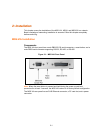
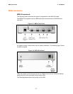
Components
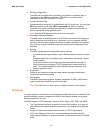
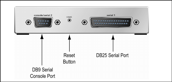
The MSS-VIA front panel has a male DB9 RS-232 serial connector, a reset button, and a
male DB25 serial connector supporting RS-232, RS-422, or RS-485.
Figure 2-1: MSS-VIA Front Panel
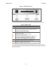
Note: When the reset button is pressed and held during the power up and boot
procedure for at least 3 seconds, the MSS-VIA returns to its factory default configuration.
The MSS-VIA rear panel has an RJ45 Ethernet connector, a PC card slot, and a power
connector.