


MSS User Guide 2: Installation
2-12
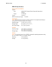
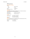
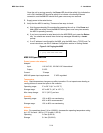
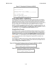
Table 2-3: MSS100 LEDs
LED Function
Power Glows green when power is supplied to the MSS.
Link
Glows green while the MSS is connected properly to a 10BASE-T or
100BASE-T Ethernet network.
100 Glows green to indicate a 100 Mb Ethernet connection.
OK Blinks yellow, green, or red to indicate MSS activity.
Serial Blinks yellow, green, or red to indicate MSS activity.
Note: Although a red LED during boot mode usually signals an error, red LED patterns
are part of the normal operation of the MSS and are not necessarily indicative of errors or
dangerous operation.
Installation Procedure
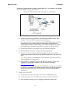
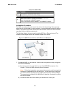
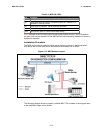
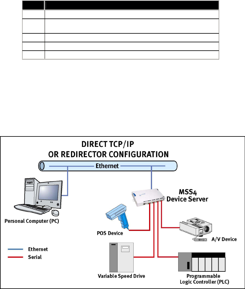
The MSS can be used to network-enable serial devices as shown in the figure below.
Any device with a serial port can be connected to the network via an MSS.
Figure 2-12: MSS Network Layout
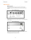
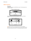
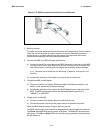
The following diagram shows a properly installed MSS. The numbers in the diagram refer
to the installation steps in this section.
MSS