


MSS User Guide 2: Installation
2-9
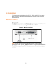
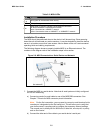
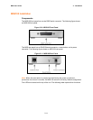
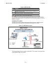
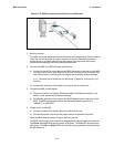
2. Connect the MSS to the network. Connect one end of a Category 5 Ethernet cable to
the Ethernet network. Connect the other end of the cable to the RJ45 Ethernet port
on the front of the MSS.
3. Supply power to the MSS. This can be done through either the MSS power jack or
the screw terminal power connector. Do not supply power to both the power jack and
the screw terminal at the same time.
a) Connect one end of a power connector to the MSS via one of the following:
Connect the barrel jack end of the power cable to the MSS power jack.
Connect power to the 9-30V screw terminal power connector and to ground and
chassis ground.
Note: The auxiliary input terminal block may be connected only to a SELV circuit.
The maximum rating is 30Vdc peak
b) Supply power to the MSS by connecting the power cube end of the power cable
to a standard wall outlet.
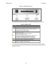
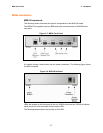
When the MSS receives power, it begins the boot process.
The MSS runs through a set of power-up diagnostics for approximately five
seconds. The OK and Serial LEDs should show varying patterns corresponding
to the test being run.
Note: If there is a valid connection to a wired Ethernet network, the Link LED should
remain solid green or yellow once the unit has completed booting.
Once the MSS is running normally, the Link LED should be solidly lit to indicate a
functioning wired Ethernet connection and the OK LED should blink once every two
seconds.
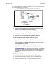
4. Supply power to the attached serial device(s), if necessary.
5. Ensure the MSS is working:
Wait approximately 30 seconds after powering the unit up. If the Link LED is
solidly lit and the OK LED blinks green once every two seconds, the MSS is
operating normally.
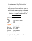
If you connected a serial terminal to the console port, press the Return key. You
should see several lines of start-up messages followed by a Local> prompt.