


MSS User Guide 2: Installation
2-2
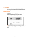
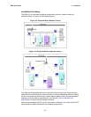
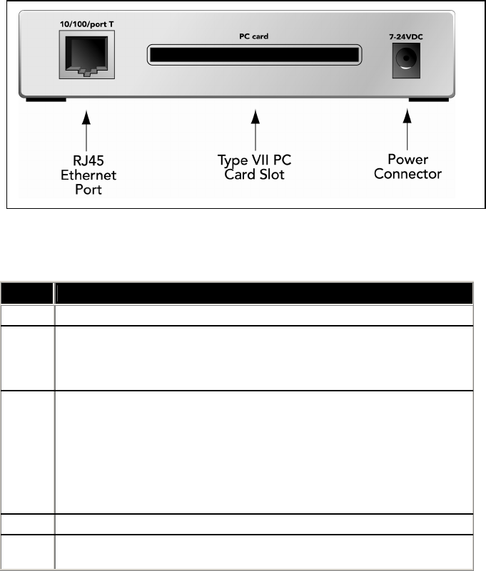
Figure 2-2. MSS-VIA Rear Panel
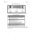
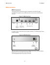
Five LEDs are located on the top of the unit. The table below explains their functions.
Table 2-1: MSS-VIA LEDs
LED Function
Serial Blinks green to indicate serial activity.
OK
Blinks green or orange/yellow to indicate network activity.
Green: Fast blink (1/2 second) -- the unit is booting; slow blink (2
seconds) -- the unit is running normally
Orange/Yellow: Packets sent or received
PC
Card
Blinks yellow, green, or red to indicate PC card status.
Off: No PC card inserted
Red blinking: PC card not read or not supported
Red solid: PC card hardware failure
Yellow blinking: Scanning for Access Point (AP) or Ad-Hoc peer
Yellow solid: PC card identified, initialization in progress
Green blinking: Negotiating settings with AP or Ad-Hoc peer
Green solid: 802.11 link established, PC card ready for use
100 Glows green to indicate a 100 Mb Ethernet connection.
Link
Glows green while the device server is connected properly to a wired
10BASE-T or 100BASE-T Ethernet network.
Note: Although a red LED during boot mode usually signals an error, red LED patterns
are part of the normal operation of the MSS and are not necessarily indicative of errors or
dangerous operation.