


MSS User Guide 2: Installation
2-13
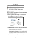
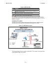
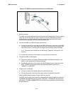
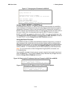
Figure 2-13: MSS Connected to Serial Device and Ethernet
1. Select a location.
The MSS should be positioned close to the device it will be servicing. Since powering
down the unit will terminate any active sessions, it may be desirable to place the
device server in a location secure from user access. Also be aware of the unit’s
environmental operating limits and cabling requirements.
2. Connect the MSS to an RS232-based serial device.
a) Connect one end of a serial cable to the DB25 connector on the front of the MSS.
You may want to use a serial terminal for the first connection both to ensure that
your device server is working and to configure the necessary network settings.
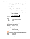
Note: The serial port is initially set for 9600 baud, 8 data bits, one stop bit, and
no parity.
b) Connect the other end of the cable to your serial device’s serial port.
3. Connect the MSS to the Ethernet.
a) Connect one end of a Category 5 Ethernet cable to the Ethernet network via a
switch or hub, depending on network topology.
b) Connect the other end of the cable to the RJ45 Ethernet port on the back of the
MSS. The MSS autosenses whether the attached Ethernet connection is
10BASE-T or 100BASE-T.
4. Supply power to the MSS.
a) Connect one end of the power cable to the MSS power jack.
b) Connect the power cube end of the power cable to a standard wall outlet.
When the MSS receives power, it begins the boot process.
The MSS runs through a set of power-up diagnostics for approximately five seconds.
The Power and Link LEDs should remain solid green. The Link LED should remain
solid green. The OK and Serial LEDs should show varying patterns corresponding to
the test being run.