


MSS User Guide 2: Installation
2-11
MSS100 Installation
Components
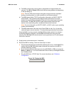
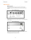
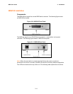
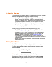
The MSS100 front panel has a male DB25 serial connector. The following figure shows
an MSS100 front panel.
Figure 2-10: MSS100 Front Panel
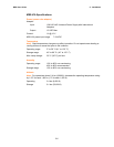
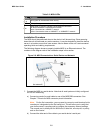
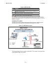
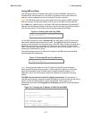
The MSS rear panel has an RJ45 Ethernet connector, a reset button, and a power
connector. The following figure shows an MSS100 rear panel.
Figure 2-11: MSS100 Rear Panel
Note: When the reset button is pressed and held during the power up and boot
procedures for at least 3 seconds, the MSS100 returns to its factory default configuration.
Five LEDs are located on the top of the unit. The following table explains their functions.