Pre-Installation Guidelines
7
3.0 PRE-INSTALLATION GUIDELINES
3.1 Room Preparation
• Verify that the floor is level, solid and sufficient to support the unit. See Table 2 for unit weights.
• Confirm that the room is properly insulated and has a sealed vapor barrier.
• For proper humidity control, keep outside or fresh air to an absolute minimum (less than 5% of
total air circulated in the room).
• Do not install Liebert DS units in an alcove or at the end of a long, narrow room.
• Install the units as close as possible to the largest heat load.
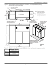
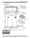
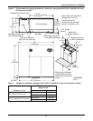
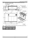
• Allow at least the minimum recommended clearances for maintenance and service. See
Figures 6 through 21 for dimensions.
• Emerson recommends installing an under-floor water detection system. Contact your local Emer-
son representative for information.
3.2 Air Distribution—Downflow Units
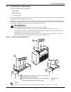
• Verify that the raised floor has been properly sized for the unit’s airflow and the room is free of
airflow restrictions.
• Perforated floor tiles in the raised floor should ensure minimal pressure loss.
• The raised floor must provide 7-1/2" (191mm) of clearance.
• Ensure that there is adequate clearance above the unit for service, such as replacing filters.
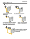
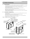
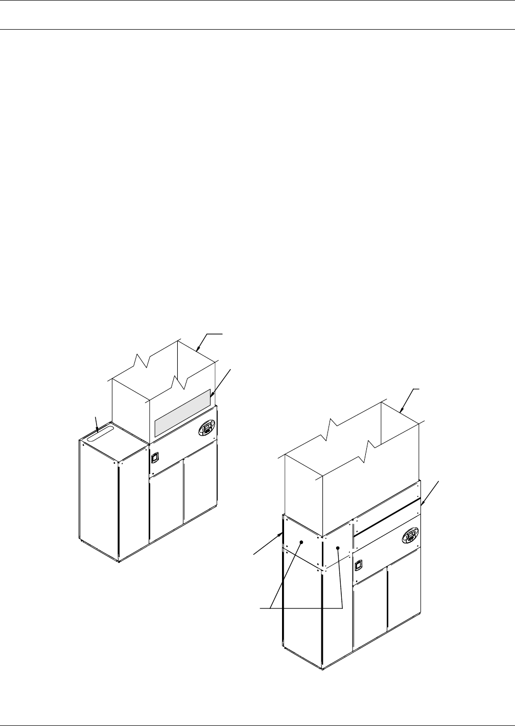
• Optional plenums are available for downflow unit ducting.
Figure 4 Downflow unit ducting and plenum ducting
Provided Condenser
Access (water, glycol
and GLYCOOL
units only)
Provided Condenser
Access (water, glycol
and GLYCOOL units only)
Provided Service
Access Door for
filter replacement
Optional
Liebert
Plenum
Liebert Plenum - Refer to plenum
installation sheet 186582P1
included in the plenum package.
Field-Fabricated
Ductwork
Field-Fabricated
Ductwork
DIRECT UNIT DUCTING
PLENUM DUCTING
Field Service Access
for filter replacement
(minimum height of
12" [305mm]; minimum
distance from unit,
2" [51mm])


