Piping Schematics
82
9.0 PIPING SCHEMATICS
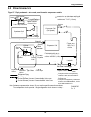
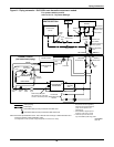
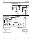
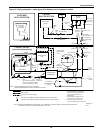
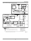
Figure 57 Piping schematic—air-cooled, semi-hermetic compressor models
Condenser Coil
(Lee-Temp)
Condenser Coil
(Fan Speed)
Check Valve
Relief Valve
Service
Valve
Liquid Return
Head Pressure
Control Valve
Lee-Temp Receiver
Hot Gas Discharge
Evaporator Coil
Lee-Temp
Compressor
Muffler
Service
Valve
External
Equalizer
Liquid
Sensing
Bulb
Inverted trap on discharge and liquid
lines to extend above base of coil by
a minimum of 7-1/2” (190mm).
Field-installed relief valve (s)
required for 50Hz EU CE units rated
maximum 480 PSIG (33 Bar).
* Isolation
valve
* Isolation
valve
** Muffler
* Traps every
25ft (7 .6m)
of rise
Fusible
Plug
Suction
Hot Gas Discharge
Liquid Return
Filter Dryer
Sight Glass
Solenoid
Valve
Expansion
Valve
Refrigerant Piping
Field Piping
Service/Schrader (Access) Connection No Valve Core
Note: Schematic representation shown . Do not use for specific connection locations .
Two refrigeration circuits provided . Single refrigeration circuit shown for clarity .
Service
Valve
Cylinder
Unloader (s)
DPN000797
Rev. 3
Service/Schrader (Access) Connection With Valve Core
Components are not supplied by
Liebert, but are recommended for
proper circuit operation and
maintenance.
Components supplied by Liebert and
must be field-installed (70kW, 77kW
and 105kW models only).
*
**


