Disassembling the Liebert DS for Transport
56
6.5 Disassembly—Upflow Units
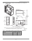
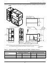
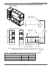
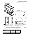
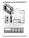
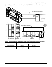
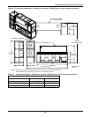
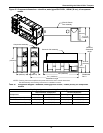
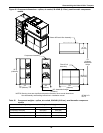
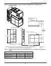
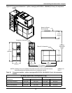
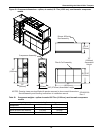
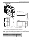
For detailed views of upflow units, see Figures 46 through 54.
1. Remove the unit from its skid.
2. Remove all panels except top front accent.
3. Remove all filters on front return units. This allows easier access to items located in the filter and
coil assembly.
4. All wires are hot stamped and all circuit board connectors are lettered for easy replacement.
Cable ties will need to be cut and replaced as necessary. Reference unit wiring schematic on
deadfront panel for details.
5. Label the (3) quick connect plugs from the compressor compartment, and disconnect them.
6. Disconnect compressor wire harness, including crankcase heater wires, if applicable, from
contactor in electric box. Pull conduit and wires into compressor compartment.
7. Reheat (optional component): Disconnect reheat wire harness from bottom of contactor in
electric box. Unplug low-voltage quick connect for reheat safety wires. Pull conduit and wires into
filter and coil assembly section of unit.
8. Humidifier (optional component): Disconnect humidifier wire harness from bottom of
contactor in electric box. Remove humidifier low-voltage connections 35-5 and 35-6 by
disconnecting quick connect plug, disconnect 35-3 and 35-4 from control board. Pull conduit and
wires into filter and coil assembly section of unit.
9. Condensate pump (optional component): Disconnect condensate pump high-voltage wire
harness. Remove low volt wires from terminal strip #24 and #55. Pull conduit and wires into filter
and coil assembly section of unit.
10. Glycool/Dual-Cool (optional component): On units with actuator, unplug valve actuator
harness at actuator and pull wire harness into electric box. Disconnect glycol sensor from control
board and pull into filter and coil assembly section of unit.
11. Smoke detector (optional component): For units with smoke detector, remove cover on smoke
detector. Remove plug connector from smoke detector and pull into electric box. Remove wires
from terminal strip #91, 92, 93 and route the wires to the smoke detector box. Remove the sensing
tube from the bottom of the plastic elbow.
12. Filter Clog Switch: Disconnect both tubes from the filter clog switch. Pull both of the tubes into
the electric box.
13. Close the electric box cover and the accent panel.
14. Remove the pull bar that supports the accent panel from left end of unit, otherwise it will fall out
when the compressor section is removed.
15. Evacuate and recover all refrigerant from the unit.
Air-cooled units contain a nitrogen holding charge. Water, glycol and GLYCOOL units are factory
charged with refrigerant. Refer to 8.0 - Piping for piping guidelines and to the ASHRAE Refrig-
eration Handbook for general, good-practice refrigeration piping.
NOTICE
Risk of compressor oil contamination with moisture.
Emerson recommends front-seating the compressor service valves. Front-seating the valves
keeps the nitrogen or refrigerant charge in the compressor and prevents moisture from
contaminating the compressor oil. This is particularly important with units using R-407C
refrigerant.
16. Cut and pull back insulation from piping.
17. Cut the refrigerant piping with a tubing cutter; if there is no Schrader fitting, let the nitrogen
bleed out before cutting all the way through the pipe.
18. Unsweat or cut all copper water pipes that interconnect unit sections.
NOTE
Emerson does not recommend unsweating refrigerant connections.


